Audi Q5: Dynamic Steering
Overview - Dynamic Steering
 Note
Note
Additional information on dynamic steering can be found in Audi Dynamic Steering Self Study Program No. 402.
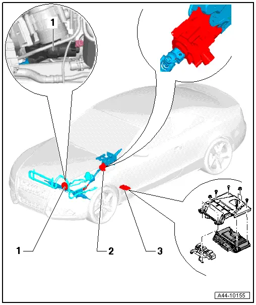
1 - Power Steering Pump
- With an electric control valve depending on the engine
- The control valve is installed in gasoline engines only.
- The power steering pump and control valve are one component and are replaced together.
- On 4- and 6-cylinder vehicles: installed on the front of the engine on the left side (belt drive)
2 - Actuator
- Must not be loosened or removed from the steering column.
- The actuator and steering column are one component and are replaced together.
- The system must be calibrated if the actuator is replaced. Refer to → Chapter "Dynamic Steering Basic Setting".
- Removing and installing. Refer to → Chapter "Steering Column, Removing and Installing"
3 - Active Steering Control Module -J792-
- The system must be calibrated if the Active Steering Control Module -J792-. Refer to → Chapter "Dynamic Steering Basic Setting".
- Removing and installing. Refer to → Chapter "Active Steering Control Module -J792-, Removing and Installing"
Active Steering Control Module -J792-, Removing and Installing
Special tools and workshop equipment required
- Torque Wrench 1783 - 2-10Nm -VAG1783-
Removing
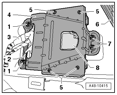
The Active Steering Control Module -J792- is located in the left footwell under the driver seat.
Before removing control module, read out code using Guided Fault Finding in "Replace control module" function.
- Loosen the driver seat and slide it back with the wires connected.
- Remove the sill panel strip. Refer to → Body Interior; Rep. Gr.70; Passenger Compartment Trim; Sill Panel Strip, Removing and Installing.
- Remove the foot rest. Refer to → Body Interior; Rep. Gr.70; Passenger Compartment Trim; Foot Rest, Removing and Installing.
- Disengage the carpet and support it using a suitable wood block -6-.
- Remove the nuts -7-.
- Remove the nuts -1- and remove the ground wire -2- from the threaded pin.
- Carefully disconnect the wiring harness clip connection -3- from the bracket -4-.
- Remove the wiring harness connectors -3- from the control module -8-.
- Remove the bolts -5- from the control module -8- and remove the bracket -4-.

Installing
Install in reverse order of removal. Note the following:
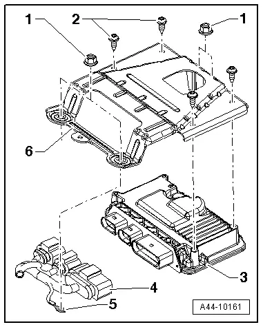
Follow the sequence when installing the control module:
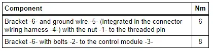
- Tighten the bracket -4- with the bolts -5- to the control module -8- to 8 Nm.
- Connect the wiring harness connectors -3- to the control module -8-.
- Carefully slide the wiring harness clip connection -3- into the bracket -4-.
- Insert the control module with the bracket.
- Connect the ground wire -2- to the threaded pin and tighten the nuts -1- to 6 Nm.
- Tighten the nuts -7- to 6 Nm.
- The system must be calibrated if the Active Steering Control Module -J792-. Refer to → Chapter "Dynamic Steering Basic Setting".
Tightening specifications:
Dynamic Steering Basic Setting
Special tools and workshop equipment required
- Vehicle Diagnostic Tester
- Steering Wheel Scales -VAS6458-
- Wheel Alignment Computer
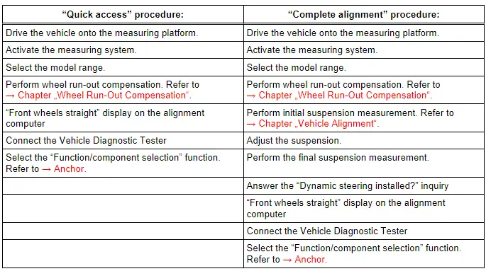
There are two choices for performing a basic setting on the dynamic steering:
The "quick access"
This procedure should be selected for the following activities if:
- the Active Steering Control Module -J792- was replaced,
- the Steering Angle Sensor -G85- was calibrated,
- the steering column was replaced,
- the steering wheel is at an angle when driving straight.
The "complete alignment"
This procedure should be selected for the following activities if:
- the suspension was adjusted during an axle alignment,
- the front axle toe was adjusted,
- the rear axle toe was adjusted,
- the vehicle suspension was changed, for example, changing from standard to sport suspension.
 Note
Note
- Both procedures are programmed into the axle alignment computer.
- The respective procedure is performed automatically.
- It is only necessary to select the appropriate program for the procedure that will be performed.
 Note
Note
- Before beginning the basic setting, check the DTC memory and correct any malfunctions present.
- Before starting the basic setting, the Steering Angle Sensor -G85- must be calibrated using the Steering Wheel Scales -VAS6458-.
- Connect the battery charger. Refer to → Electrical Equipment; Rep. Gr.27; Battery; Battery, Charging.
- Connect the Vehicle Diagnostic Tester to the vehicle.
- Select the calibration procedure for dynamic steering in the alignment computer.
- Install the quick clamps on all four wheels.
- Install the measurement sensors on the front and rear wheels.
- Perform wheel run-out compensation. Refer to → Chapter "Wheel Run-Out Compensation".
- Position the wheels so they are straight according to the alignment computer.
 Note
Note
- Disregard the steering wheel position when doing this.
- Only the display on the alignment computer is valid.
Subsequent procedures are performed using the Vehicle Diagnostic Tester.
- Switch the ignition on.
- Touch Guided Fault Finding.
- Select in succession:
- Brand
- Type
- Model year
- Version
- Engine Codes
- Confirm data entered.
Wait until the Vehicle Diagnostic Tester has check all the control modules in the vehicle.
- Press the go to button and select "function/component selection".
- Select the corresponding program in "Guided Functions".
Now follow the instructions on the screen to perform the basic setting.

