Audi Q5: Adaptive Cruise Control (ACC)
Overview - Adaptive Cruise Control Sensor -G550-
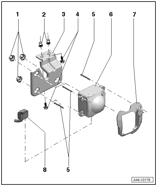
1 - Nut
2 - Threaded Sleeve
- Pressed inside the longitudinal member
3 - Bracket
- Removing and installing.
4 - Bolt
- 8 Nm
5 - Stud Bolt
- Observe adjustment dimension when installing. Refer to → Fig. "Measure dimension -a- of all studs."
6 - Adaptive Cruise Control Sensor -G550-
- Removing and installing. Refer to → Chapter "Adaptive Cruise Control Sensor -G550-, Removing and Installing"
7 - Sensor Cover
- Removing and installing.
8 - Connector
Adaptive Cruise Control Sensor -G550-, Removing and Installing
The Adaptive Cruise Control Sensor -G550- is located behind the right air intake grille in the front bumper.
Special tools and workshop equipment required
- Torque Wrench 1783 - 2-10Nm -VAG1783-
Removing
Adaptive Cruise Control Sensor -G550-, removing without bracket
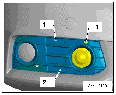
- Release the bracket -1- and remove the air intake grille -2-.
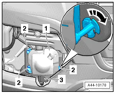
- Turn the nuts -2- approximately 45º in direction of -arrow- and remove the Adaptive Cruise Control Sensor -G550--1- with the stud bolts from the nuts -2-.
- Release the connector -3- and remove it from the Adaptive Cruise Control Sensor -G550--1-.
- Remove the Adaptive Cruise Control Sensor -G550--1- forward through the bumper cover.
Adaptive Cruise Control Sensor -G550-, removing with bracket
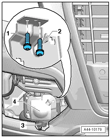
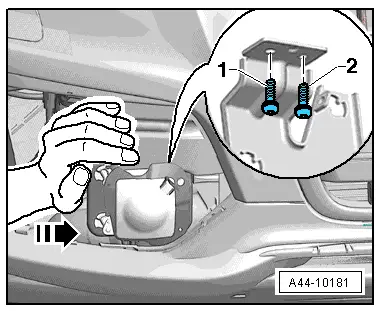
- Remove the screws -1- and -2-, disconnect the connector -3-, free up the wiring harness and remove the Adaptive Cruise Control Sensor -G550--4- with the bracket through the bumper cover.
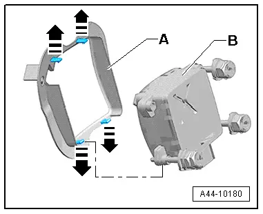
Remove the cover from the Adaptive Cruise Control Sensor -G550-.
- Release the clips -arrows- and remove the cover -A- from the Adaptive Cruise Control Sensor -G550--B-.
Installing
Install in reverse order of removal. Note the following:
Studs in bracket are preset. If necessary, correct adjustment.
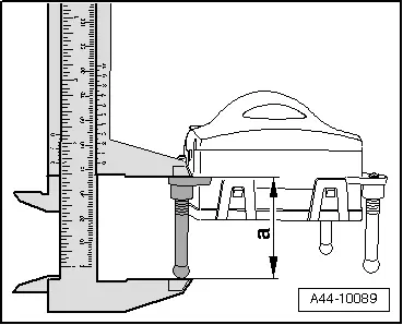
- Place the Adaptive Cruise Control Sensor -G550- on a soft, clean cloth.
Measure dimension -a- of all studs.
Dimension -a- must be 43 mm.
- Insert bracket and tighten bolts.
 Note
Note
While installing the bracket for the Adaptive Cruise Control Sensor -G550-, position it facing the center of the vehicle (as shown) and then tighten it.
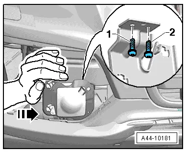
- Follow the tightening sequence:
- Install the screw -1- in the oblong hole, then install the screw -2- in the hole and tighten it. Tighten the screw -1- in the oblong hole.
- Install the Adaptive Cruise Control Sensor -G550- and carefully push three nuts by hand onto the stud bolts in the sensor.
- Install the air intake grille. Refer to → Body Exterior; Rep. Gr.63; Front Bumper.
- Calibrate the adaptive cruise control. Refer to → Chapter "Adaptive Cruise Control (ACC), Calibrating, Calibration Procedure with Setting Device Basic Set -VAS6430/1-".
Setting Device Basic Set -VAS6430/1- Converting for the Adjustment Procedure
Special tools and workshop equipment required
- Setting Device Basic Set -VAS6430/1-
Before performing the adjustment, check in which mount the vertical slits on the Setting Device Basic Set -VAS6430/1- are located. The Setting Device Basic Set -VAS6430/1- may have to be adapted before performing adjustment.
The Setting Device Basic Set -VAS6430/1- must be adapted before the adjustment procedure. If this is done during the adjustment procedure, the pre-calibration on the Setting Device Basic Set -VAS6430/1- must be repeated.
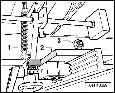
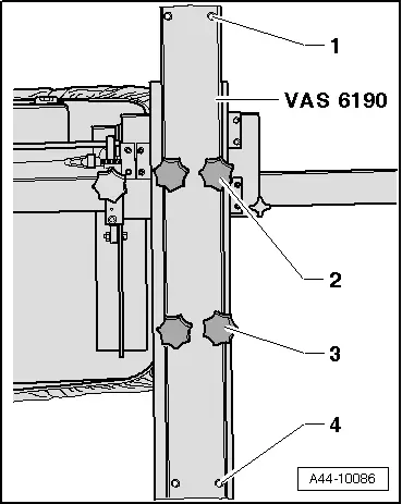
- For the adjustment procedure, the vertical slits in mounts -1- through -4- must be inserted so that laser beam is approximately centered vertically when it contacts the sensor lens.
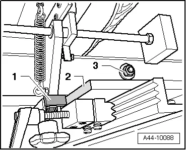
- The original nut at the top of the horizontal slits must be replaced with a standard nut -3-.
 Note
Note
The original nut at the top of the horizontal slits must be replaced with a standard nut so that the mirror can be slide far enough to the center.
- The mirror at the center -1- must be removed and installed again all the way to the left -arrow- near the vertical slits -2-.
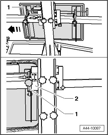
- Then the mirror -1- must be slide on horizontal slits as far as stop on vertical slits -2-.
