Audi Q5: Control Arm, Removing and Installing
Special tools and workshop equipment required
- Engine and Gearbox Jack -VAS6931-
- Puller - Ball Joint -T40010A-
- Torque Wrench 1332 Insert - Ring Wrench - 18mm -VAG1332/10- or
- Torque Wrench 1332 Insert - Ring Wrench - 21mm -VAG1332/7-
Removing
- Remove the wheel.
- Remove the noise insulation. Refer to → Body Exterior; Rep. Gr.66; Noise Insulation.
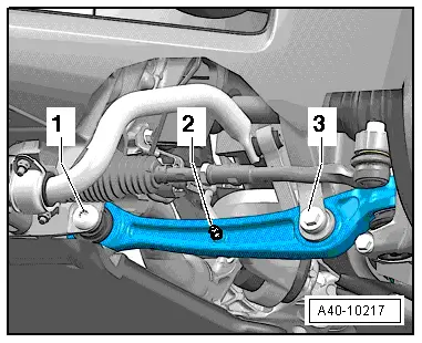
- In vehicles with level control system sensor, unscrew nut -2-.
- Disconnect the bolting -3-.

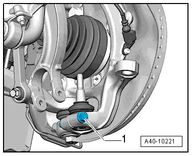
- Remove the nut -1- from the tie rod end joint pin -2- until it is flush with the joint pin threads. Counterhold when loosening if necessary.
 Note
Note
To protect thread, screw nut on pin a few turns.
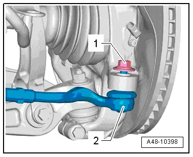
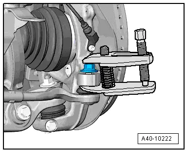
- Remove the tie rod end from the wheel bearing housing using the Puller - Ball Joint -T40010A-. Remove the nut.
 Note
Note
Make sure that both puller lever arms are parallel to each other when using greatest force, adjust if necessary.
- Disconnect the threaded connection -1-.
 Note
Note
To remove the bolt -1-, turn the steering gear all the way to the left or right depending on the side of the vehicle.
- Remove the control arm from the subframe and move it to the rear.
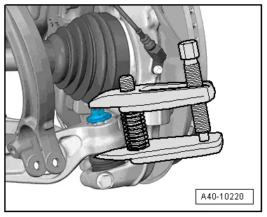
- Remove the nut from the ball joint pins just enough so it is flush with the joint pin threads. Counterhold when loosening if necessary.

- Press the control arm joint pin off the conical seat using the Puller - Ball Joint -T40010A-.
 Note
Note
- Make sure that both puller lever arms are parallel to each other when using greatest force, adjust if necessary.
- Be careful not to damage CV boot in the process!
- In order to not damage the joints of the upper control arms, the wheel bearing housing must be braced against too strong rebound using the Engine and Gearbox Jack -VAS6931-, for example.
- Remove the nut from the control arm joint pin.
- Remove track control arm.
Installing
Install in reverse order of removal. Note the following:
Tightening specifications. Refer to → Chapter "Overview - Lower Control Arm and Ball Joint".
 Note
Note
- Bonded rubber bushings have a limited range of motion. Only tighten suspension screws when vehicle is in curb weight or control position.
- Tightening specifications. Refer to → Chapter "Overview - Lower Control Arm and Ball Joint".
- When tightening the threaded connection -1-, the control arm must be pressed toward the inside of the vehicle.
- Remove the adhesive residue from the ball joint stub thread.
- On vehicles with automatic head lamp range control, perform headlamp basic setting. Refer to → Electrical Equipment; Rep. Gr.94; Headlamps; Headlamp, Adjusting.
- If the level control system sensor was removed and installed on a vehicle with electronically controlled damping or if the linkage was loosened, the control position must be reprogrammed using the Vehicle Diagnostic Tester. Refer to → Chapter "Control Position, Programming".
- If the control position was reprogrammed on vehicles with lane assist, the Directional Stabilization Assistance Control Module -J759- must be calibrated again. Refer to → Chapter "Lane Assist, Calibrating".
- Tighten the wheel. Refer to → Chapter "Wheel Bolt Tightening Specifications".
- An axle alignment may be required. Refer to → Chapter "Evaluating Need for Axle Alignment".
Control Arm Ball Bearing, Replacing
Pressing out and in bearing for track control arm (on wheel bearing housing side)
Special tools and workshop equipment required
- Press Plate -VW402-
- Press Piece - Multiple Use -VW412-
- Subframe Bushing Tool Kit -3301-
- Bearing Installer - Control Arm -3346-
- Hydraulic Press - Bushing Tool Kit -T10030-
- Assembly Paste
 Note
Note
Hold track control arm firmly in position while pressing bearing out and in.
Bearing, Removing
- Remove the control arm. Refer to → Chapter "Control Arm, Removing and Installing".
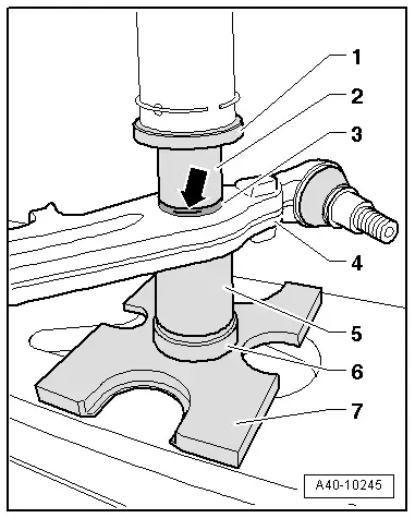
- Mark the installation depth -arrow- on the bearing -1-.
Use a waterproof felt-tip pen.
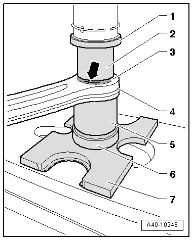
- Install the special tools as shown in the illustration.
1 - Press Piece - Multiple Use -VW412-
2 - Assembly Tool Kit - Press Piece 1 -T10030/1-
3 - Bearing
4 - Control Arm
5 - Subframe Bushing Tool Kit - Assembly Tool 3 -3301/3-
6 - Subframe Bushing Tool Kit - Bolt -3301/1-
7 - Press Plate -VW402-
- Press bearing -3- out of track control arm -4-.
Bearing Race, Installing
- Transfer the installation depth marking from the old bearing to the new one.
- Lightly coat the bearing with Fitting Paste. Refer to the Parts Catalog.
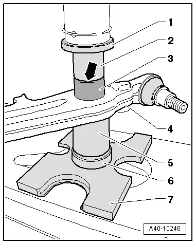
- Insert bearing -3- into track control arm -4-.
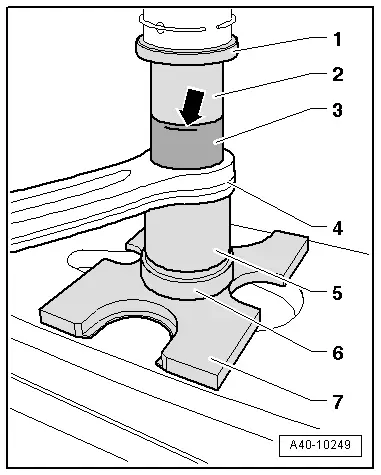
- Install the special tools as shown in the illustration.
1 - Press Piece - Multiple Use -VW412-
2 - Assembly Tool Kit - Press Piece 1 -T10030/1-
3 - Bearing
4 - Control Arm
5 - Bearing Installer - Control Arm - Bearing Installer -3346/1-
6 - Subframe Bushing Tool Kit - Bolt -3301/1-
7 - Press Plate -VW402-
 Note
Note
When installing, make sure the bearing does not tilt.
- Press the bearing -3- into track control arm -4-.
- Note the installation depth marking when installing -arrow-.
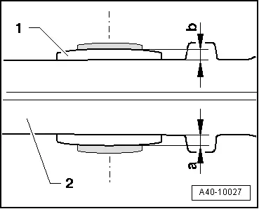
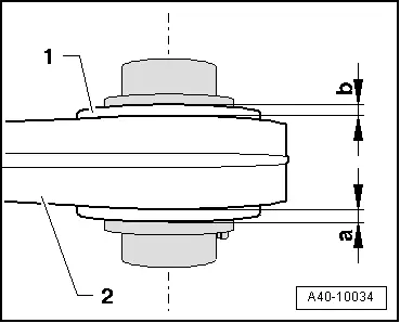
- Check rim offset of bearing -1- in track control arm -2-.
Dimensions -a- and -b- must be identical.
- If dimensions -a- and -b- are different, press the bearing -1- in more.
- Install the control arm. Refer to → Chapter "Control Arm, Removing and Installing".
Bearing for Track Control Arm (On Subframe Side), Pressing Out and Pressing In
Special tools and workshop equipment required
- Press Plate -VW402-
- Press Piece - Multiple Use -VW412-
- Subframe Bushing Tool Kit -3301-
- Bearing Installer - Control Arm -3346-
- Assembly Paste
 Note
Note
Hold track control arm firmly in position while pressing bearing out and in.
Bearing, Removing
- Remove the control arm. Refer to → Chapter "Control Arm, Removing and Installing".
- Mark the installation depth -arrow- on the bearing -3-.
Use a waterproof felt-tip pen.
- Install the special tools as shown in the illustration.
1 - Press Piece - Multiple Use -VW412-
2 - Bearing Installer - Control Arm -3346-
3 - Bearing
4 - Control Arm
5 - Subframe Bushing Tool Kit - Thrust Piece -3301/4-
6 - Subframe Bushing Tool Kit - Bolt -3301/1-
7 - Press Plate -VW402-
- Press bearing -3- out of track control arm -4-.
Bearing Race, Installing
- Transfer the installation depth marking from the old bearing to the new one.
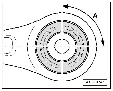
Mounting installation location
A = ~ 90º +- 5º
- Lightly coat the bearing with Fitting Paste. Refer to the Parts Catalog.
- Insert bearing -1- into track control arm -2-.
- Install the special tools as shown in the illustration.
1 - Press Piece - Multiple Use -VW412-
2 - Bearing Installer - Control Arm -3346-
3 - Bearing
4 - Control Arm
5 - Subframe Bushing Tool Kit - Assembly Tool 3 -3301/3-
6 - Subframe Bushing Tool Kit - Bolt -3301/1-
7 - Press Plate -VW402-
 Note
Note
When installing, make sure the bearing does not tilt.
- Press the bearing -3- into track control arm -4-.
- Note the installation depth marking when installing -arrow-.
- Check rim offset of bearing -1- in track control arm -2-.
Dimensions -a- and -b- must be identical.
- If dimensions -a- and -b- are different, press the bearing -1- in more.
- Install the control arm. Refer to → Chapter "Control Arm, Removing and Installing".
Ball Joint, Removing and Installing
Removing
- Remove the control arm. Refer to → Chapter "Control Arm, Removing and Installing".
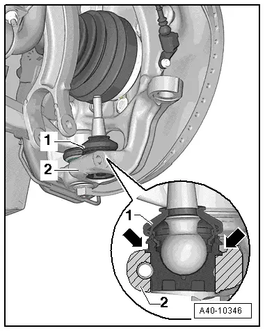
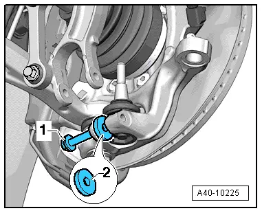
- Remove the bolt -1-.
- Insert a washer or the like -2- into the slot in the wheel bearing housing (the washer must match the width of the slot exactly).
- Install the bolt -1- until it touches the back of the washer.
- Side the wheel bearing housing slot by installing the bolt -1- further (one half turn).
- Remove the ball joint from the wheel bearing housing.
Installing
Install in reverse order of removal. Note the following:
- Install the ball joint -1- into the wheel bearing housing -2- as far as the contact surface -arrows-.
 Note
Note
If the ball joint -1- is not inserted up to the contact surface -arrows- then the threaded connection on the wheel bearing housing -2- could get damaged.
Tightening specifications. Refer to → Chapter "Overview - Lower Control Arm and Ball Joint".
- Install the control arm. Refer to → Chapter "Control Arm, Removing and Installing".
- Tighten the wheel. Refer to → Chapter "Wheel Bolt Tightening Specifications".
- An axle alignment may be required. Refer to → Chapter "Evaluating Need for Axle Alignment".