Audi Q5: Wheel Bearing Housing, Removing and Installing
Special tools and workshop equipment required
- Torque Wrench 1331 5-50Nm -VAG1331-
- Torque Wrench 1332 40-200Nm -VAG1332-
- Torque Wrench 1332 Insert - Ring Wrench - 18mm -VAG1332/10- or
- Torque Wrench 1332 Insert - Ring Wrench - 21mm -VAG1332/7-
 Note
Note
- Two different wheel bearing housings were installed in production; the difference between the two is the steering arm strength. Refer to the Parts Catalog.
- When exchanging the wheel bearing housing, make sure the length of the thread on the tie rod end is sufficient (there must be approximately 5 mm extra thread). If this is not the case, then install a new tie rod end with a longer thread pin. Refer to the Parts Catalog.
- Distinguishing characteristic.
Removing
- Loosen the connection between the drive axle and wheel hub. Refer to → Chapter "Drive Axle Threaded Connection, Loosening and Tightening".
- Remove the control arm. Refer to → Chapter "Control Arm, Removing and Installing".
- Remove brake line and electrical line bracket from wheel bearing housing.
- Remove the Front ABS Wheel Speed Sensor. Refer to → Break System; Rep. Gr.45; Sensors; Right/Left Front ABS Wheel Speed Sensor G45/G47, Removing and Installing.
- Remove brake caliper and secure to body so weight of caliper does not stress or damage brake hose or brake line.
- Remove the brake rotor.
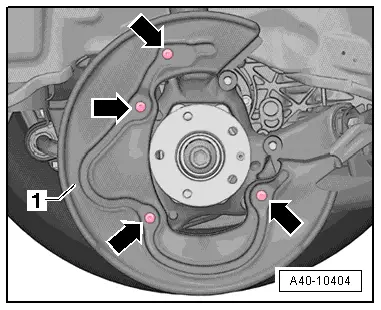
- Remove the screws -arrows- and remove the brake shield -1-.
- Remove the nut from the guide link joint pins enough so it is flush with the joint pin threads. Counterhold when loosening if necessary.
 Note
Note
To protect thread, screw nut on pin a few turns.
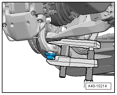
- Press the guide link joint pin off the conical seat using the Puller - Ball Joint -T40010A-.
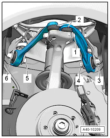
- Disconnect the threaded connection -1-.
- Remove booth joint pins in the upper control arm -2- from the wheel bearing housing.
The slits in the wheel bearing housing must not be widened using a chisel or similar tool!
- Loosen the wheel bearing housing from the drive axle splines and remove it.
 Note
Note
- The drive axle must not hang down, otherwise the inner joint will be damaged by over-flexing.
- Secure the drive axle to body using wire.
Installing
Install in reverse order of removal. Note the following:
Tightening specifications. Refer to → Chapter "Overview - Wheel Bearing".
- Slide the wheel bearing housing onto the drive axle splines.

- Insert both of upper control arm joint pins -2- in the wheel bearing housing and insert the bolt -1-.
- Remove the adhesive residue on the ball joint and guide link stub threads.
- Install the guide link on the wheel bearing housing and tighten.
- Install the control arm. Refer to → Chapter "Control Arm, Removing and Installing".

 Note
Note
Push the upper control arms down as far as possible while tightening the bolts!
- Tighten the bolting -1-.
- Install the brake rotor and the brake caliper. Refer to → Brake System; Rep. Gr.46; Front Brakes; Brake Rotor, Removing and Installing.
- Tighten the drive axle to wheel hub threaded connection. Refer to → Chapter "Drive Axle Threaded Connection, Loosening and Tightening".
- On vehicles with automatic head lamp range control, perform headlamp basic setting. Refer to → Electrical Equipment; Rep. Gr.94; Headlamps; Headlamp, Adjusting.
- If the level control system sensor was removed and installed on a vehicle with electronically controlled damping or if the linkage was loosened, the control position must be reprogrammed using the Vehicle Diagnostic Tester. Refer to → Chapter "Control Position, Programming".
- If the control position was reprogrammed on vehicles with lane assist, the Directional Stabilization Assistance Control Module -J759- must be calibrated again. Refer to → Chapter "Lane Assist, Calibrating".
- Tighten the wheel. Refer to → Chapter "Wheel Bolt Tightening Specifications".
- An axle alignment may be required. Refer to → Chapter "Evaluating Need for Axle Alignment".