Audi Q5: Component Location Overview - Storage Compartment/Covers
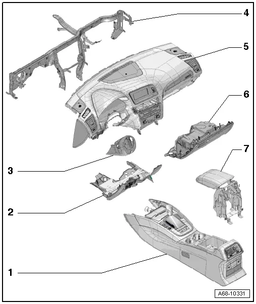
1 - Center Console
- Overview. Refer to → Chapter "Overview - Center Console".
2 - Driver Side Instrument Panel Cover
- Overview. Refer to → Chapter "Overview - Driver Side Instrument Panel Cover".
3 - Trim Panel
- For the steering column switch module
- Overview. Refer to → Chapter "Overview - Steering Column Trim Panel".
4 - Central Tube
- For the instrument panel
- Overview. Refer to → Chapter "Overview - Instrument Panel Central Tube".
5 - Instrument Panel
 WARNING
Follow all Safety Precautions when working with pyrotechnic components. Refer to → Chapter "Pyrotechnic Components Safety Precautions".
- Overview. Refer to → Chapter "Overview - Instrument Panel".
6 - Glove Compartment
- Overview. Refer to → Chapter "Overview - Glove Compartment".
7 - Front Center Armrest
- Equipment levels
- Overview. Refer to → Chapter "Overview - Front Center Armrest".
Overview - Driver Side Instrument Panel Cover
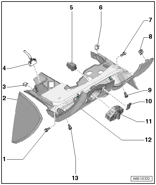
1 - Bolt
- 3 Nm
2 - Side Cover
- For the instrument panel
- Removing and installing. Refer to → Chapter "Instrument Panel Side Cover, Removing and Installing".
3 - Bracket
- Insert in the footrest
4 - 16-Pin Connector -T16-
- Data Link Connector (DLC)
5 - Headlamp Range Control Adjuster -E102-
- Equipment levels
- Removing and Installing. Refer to → Electrical Equipment; Rep. Gr.96; Controls; Headlamp Range Control Adjuster E102, Removing and Installing.
6 - Bracket
- Install on the A/C unit
7 - Bolt
- 3 Nm
8 - Spring Clip
- For the driver side instrument panel cover
- Quantity: 3
- Press into the instrument panel
9 - Bolt
- 3 Nm
10 - Trim
- For the Headlamp Range Control Adjuster -E102-
- Equipment levels
- Removing and installing. Refer to → Chapter "Headlamp Range Control Adjuster -E102- Trim, Removing and Installing".
11 - Light Switch -E1-
- Removing and Installing. Refer to → Electrical Equipment; Rep. Gr.96; Controls; Overview - Instrument Panel Controls.
12 - Driver Side Instrument Panel Cover
- There are different versions. For the correct allocation, refer to the Parts Catalog.
- Removing and installing. Refer to → Chapter "Driver Side Instrument Panel Cover, Removing and Installing".
- Equipment level with Headlamp Range Control Adjuster -E102-: After replacing the driver side instrument panel cover add the cut-out for the headlamp range control adjuster. Refer to → Chapter "Headlamp Range Control Adjuster -E102-, Making an Additional Cut-Out in Instrument Panel Cover".
13 - Bolt
- 3 Nm
Overview - Steering Column Trim Panel
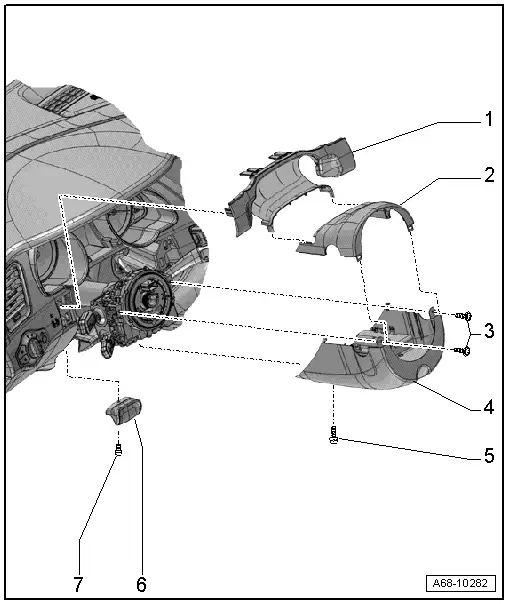
1 - Gap Cover
- for instrument cluster
- Removing and installing. Refer to → Chapter "Instrument Cluster Gap Cover, Removing and Installing".
2 - Upper Trim
- For the steering column switch module
- Removing and installing. Refer to → Chapter "Upper Steering Column Trim Panel, Removing and Installing".
3 - Bolts
- 2.0 Nm
4 - Lower Trim
- For the steering column switch module
- Removing and installing. Refer to → Chapter "Lower Steering Column Trim Panel, Removing and Installing".
5 - Bolt
- 2.0 Nm
6 - Handle
- for the steering column adjustment
- Equipment levels
7 - Bolt
- 3 Nm
Overview - Glove Compartment
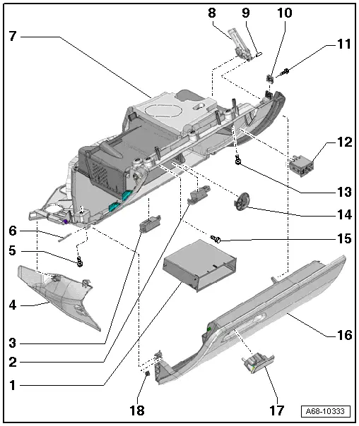
1 - Storage Compartment
- Equipment levels
- Removing and installing. Refer to → Chapter "Glove Compartment Storage Compartment, Removing and Installing".
2 - Glove Compartment Lamp -W6-
- Removing and Installing. Refer to → Electrical Equipment; Rep. Gr.96; Lamps; Glove Compartment Lamp W6, Removing and Installing.
3 - Footwell Lamp
- Equipment levels
- Removing and installing. Refer to → Electrical Equipment; Rep. Gr.96; Lamps; Left/Right Front Footwell Illumination Bulb L151/L152, Removing and Installing
4 - Passenger Side Instrument Panel Cover
- Removing and installing. Refer to → Chapter "Front Passenger Side Instrument Panel Cover, Removing and Installing".
5 - Bolt
- 3 Nm
- Quantity: 2
6 - Hinge Pin
- For securing the glove compartment cover
7 - Glove Compartment
- Removing and installing. Refer to → Chapter "Glove Compartment, Removing and Installing".
8 - Brake Component
- For the glove compartment lid
- With Glove Compartment Lamp Switch -E26-
- Removing and installing. Refer to → Chapter "Glove Compartment Lid Braking Element, Removing and Installing".
9 - Hinge Pin
10 - Spring Nut
11 - Bolt
- 3 Nm
12 - Front Passenger Airbag Deactivation Key Switch -E224-
- Not for North American market.
13 - Bolt
- 3 Nm
- Quantity: 4 or 5 depending on the country
14 - Cold Air Vent/Blind Cover
- Equipment levels
15 - Bolt
- 3 Nm
- The quantity depends on the equipment level or the country
16 - Glove Compartment Cover
- Removing and installing. Refer to → Chapter "Glove Compartment Lid, Removing and Installing".
17 - Glove Compartment Opener
- Removing and installing. Refer to → Chapter "Glove Compartment Handle, Removing and Installing".
18 - Stop Buffer
- For the glove compartment lid

