Audi Q5: Component Location Overview - Sound System
Component Location Overview - Sound System, Basic/Standard
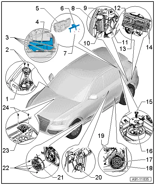
1 - Left Front Treble Speaker -R20-/Right Front Treble Speaker -R22-
- Removing and installing. Refer to → Chapter "Front Treble Speaker, Removing and Installing".
2 - Bolt
- 1 Nm
3 - Bolt
- 5 Nm
4 - Subwoofer in Rear Shelf -R157- (High Voltage Vehicle)
- Removing and Installing, High Voltage Vehicle. Refer to → Chapter "Subwoofer in Rear Shelf -R157-, Removing and Installing, High Voltage Vehicle"
5 - Subwoofer in Rear Shelf -R157- (High Voltage Vehicle)
6 - Support (High Voltage Vehicle)
7 - Bolt
- 2 Nm
8 - Digital Sound System Control Module -J525-
- Connector Assignment (CAN). Refer to → Chapter "Sound System Connector Assignments Standard, CAN".
- CAN, Removing and Installing. Refer to → Chapter "Digital Sound System Control Module -J525-, Removing and Installing, CAN"
- MMI, Removing and Installing. Refer to → Chapter "Digital Sound System Control Module -J525-, Removing and Installing, MMI".
9 - Nut
- 3 Nm
10 - Nut
- 3 Nm
11 - Nut
- 3 Nm
12 - Bolt
- 3.5 Nm
13 - Digital Sound System Control Module -J525-
14 - Bolt
- 3.5 Nm
15 - Bolt
- 2 Nm
16 - Subwoofer in Rear Shelf -R157-
- Removing and installing. Refer to → Chapter "Subwoofer In Rear Shelf -R157-, Removing and Installing".
17 - Left Rear Mid-Bass Speaker -R159-/Right Rear Mid-Bass Speaker -R160-
- Removing and installing. Refer to → Chapter "Rear Mid-Bass Speaker, Removing and Installing".
18 - Bolt
- 3 Nm
19 - Bolt
- 3 Nm
20 - Left Rear Treble Speaker -R14-/Right Rear Treble Speaker -R16-
- Removing and installing. Refer to → Chapter "Left/Right Rear Treble Speaker -R14-/-R16-, Removing and Installing".
21 - Left Front Mid-Bass Speaker -R101-/Right Front Mid-Bass Speaker -R102-
- Removing and installing. Refer to → Chapter "Front Mid-Bass Speaker and Front Bass Speaker, Removing and Installing".
22 - Bolt
- 3 Nm
23 - Center Mid-Treble Speaker -R158-
- Removing and installing. Refer to → Chapter "Center Mid-Treble Speaker -R158-".
24 - Bolt
- 1 Nm
Component Location Overview - Sound System, Premium, Bang & Olufsen
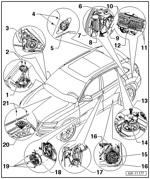
1 - Left Front Midrange Speaker -R103-/Right Front Midrange Speaker -R104-
- Removing and installing. Refer to → Chapter "Front Midrange Speaker, Removing and Installing, Bang & Olufsen".
2 - Bolt
- 1 Nm
3 - Left Front Treble Speaker -R20-/Right Front Treble Speaker -R22-
- Removing and installing. Refer to → Chapter "Front Treble Speaker, Removing and Installing, Bang & Olufsen".
4 - Bolt
- 2 Nm
5 - Left Rear Midrange Speaker -R105-/Right Rear Midrange Speaker -R106-
- Removing and installing. Refer to → Chapter "Rear Midrange Speaker, Removing and Installing".
6 - Nut
- 3 Nm
7 - Digital Sound System Control Module -J525-
- Connector Assignment B+O (CAN). Refer to → Chapter "Sound System Connector Assignments, Bang & Olufsen, CAN".
- Connector Assignment B+O (MMI). Refer to → Chapter "Sound System Connector Assignments, Bang & Olufsen, MMI".
- CAN, Removing and Installing. Refer to → Chapter "Digital Sound System Control Module -J525-, Removing and Installing, CAN"
- MMI, Removing and Installing. Refer to → Chapter "Digital Sound System Control Module -J525-, Removing and Installing, MMI".
8 - Nut
- 3 Nm
9 - Nut
- 3 Nm
10 - Bolt
- 3.5 Nm
11 - Bolt
- 3.5 Nm
12 - Digital Sound System Control Module -J525-
13 - Bolt
- 2 Nm
14 - Subwoofer in Rear Shelf -R157-
- High voltage vehicle -item 4-
- Support (High Voltage Vehicle) -item 6-
- Removing and installing. Refer to → Chapter "Subwoofer In Rear Shelf -R157-, Removing and Installing".
- Removing and Installing, High Voltage Vehicle. Refer to → Chapter "Subwoofer in Rear Shelf -R157-, Removing and Installing, High Voltage Vehicle"
15 - Left Rear Mid-Bass Speaker -R159-/Right Rear Mid-Bass Speaker -R160-
- Removing and installing. Refer to → Chapter "Rear Mid-Bass Speaker, Removing and Installing".
16 - Bolt
- 3 Nm
17 - Left Rear Treble Speaker -R14-/Right Rear Treble Speaker -R16-
- Removing and installing. Refer to → Chapter "Left/Right Rear Treble Speaker -R14-/-R16-, Removing and Installing".
18 - Left Front Bass Speaker -R21-/Right Front Bass Speaker -R23-
- Removing and installing. Refer to → Chapter "Front Mid-Bass Speaker and Front Bass Speaker, Removing and Installing".
19 - Bolt
- 3 Nm
20 - Center Mid-Treble Speaker -R158-
- Removing and installing. Refer to → Chapter "Center Mid-Treble Speaker -R158-".
21 - Bolt
- 1 Nm

