Audi Q5: Bulkhead
Overview - Bulkhead
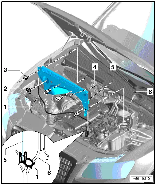
1 - Seal
- Install the seal from underneath.
2 - Lock Washer
- When installing, simply press the plenum chamber bulkhead onto the threaded pins.
3 - Nut
- 4 Nm
4 - Bolt
- 7 Nm
5 - Plenum Chamber Bulkhead
High-Voltage System Vehicles (Hybrid Vehicles):
DANGER!
Extremely dangerous high-voltage
Electrocution can cause death or very serious personal injury.
- The high-voltage system may only be de-energized by an appropriately qualified technician (Audi high-voltage technician) .
- It must be certain that the voltage for the high-voltage system is de-energized. Ensuring the system is de-energized can only be done using the Vehicle Diagnostic Tester via "Guided Fault Finding".
- The qualified technician (Audi high-voltage technician) will make sure the voltage is turned off and that the system cannot turn back on again using a Service Disconnect Lock - T40262-. The qualified technician should make sure the system cannot re-energize by keeping the key and the High-Voltage System Maintenance Connector -TW- in a safe place.
- The qualified technician (Audi high-voltage technician) marks the vehicle with a label.
 Note
Note
- De-energizing the high-voltage system:
- Connect the Vehicle Diagnostic Tester
- Select the Guided fault finding mode
- Using the Go To button, move through the following menu points
- Function/component selection
- Body
- Electrical Equipment
- OBD-capable system
- 8C - hybrid battery management -J840
- 8C - hybrid battery management, functions
- 51 - De-energizing the high-voltage system (Repair Group 93)
Read all warning messages for the vehicle when working on a vehicle with the high-voltage system.
 Note
Note
When removing, remember there are different versions.
- Before removing:
- Remove the tower brace. Refer to → Suspension, Wheels, Steering; Rep. Gr.40; Suspension Strut, Upper Control Arm; Tower Brace, Removing and Installing.
- Disconnect the vacuum line to the brake booster at the connection to the plenum chamber bulkhead.
- Unclip the vacuum line from the plenum chamber bulkhead.
- Disconnect the Terminal 30 Wire Junction 2 - TV22- from the plenum chamber bulkhead and free up the wires.
- Drain the coolant. Refer to → Rep. Gr.19; Coolant System/Coolant; Coolant, Draining and Filling.
- Disconnect the coolant hoses to the heater core.
- Press the coolant hoses with hose guide in the plenum chamber.
Vehicles with High-Voltage System (Hybrid Vehicle)
- Disconnect the high-voltage cables at the Electric Drive Power and Control Electronics - JX1-. Refer to → Electrical System Hybrid; Rep. Gr.93; High-Voltage Cables; Overview - High-Voltage Cable Component Locations.
Continuation for All Vehicles:
- To remove, remove the bolts -4- and nut -3-.
- Install in reverse order of removal.
 DANGER!
Extremely dangerous high-voltage
Severe bodily injury or death by electrocution
- The high-voltage system may only be re-energized by an appropriately qualified technician (Audi high-voltage technician).
- Ensuring the system is re-energized can only be done using the Vehicle Diagnostic Tester via "Guided Fault Finding ".
- The qualified technician (Audi high-voltage technician) restarts the vehicle.
- The qualified technician (Audi high-voltage technician) marks the vehicle with a label.
 Note
Note
- Energizing the high-voltage system:
- Connect the Vehicle Diagnostic Tester
- Select the Guided fault finding mode
- Using the Go To button, move through the following menu points
- Function/component selection
- Body
- Electrical Equipment
- OBD-capable system
- 8C - hybrid battery management -J840
- 8C - hybrid battery management, functions
- 51 - Energizing the high-voltage system (Rep.Gr. 93)
6 - Plenum Chamber
Overview - Additional Reinforcement
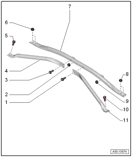
1 - Bolt
- 30 Nm
2 - Nut
- 2.5 Nm
3 - Bolt
- 30 Nm
4 - Right Reinforcement
- For the tower brace
- Removing and installing. Refer to → Chapter "Tower Brace Reinforcement, Removing and Installing".
5 - Bolt
- 30 Nm
6 - Nut
- Quantity: 2
- 30 Nm
7 - Tower Brace
- Removing and Installing. Refer to →Suspension, Wheels, Steering; Rep. Gr.40.
8 - Nut
- 30 Nm
- Quantity: 2
9 - Nut
- 2.5 Nm
10 - Bolt
- 30 Nm
11 - Left Reinforcement
- For the tower brace
- Removing and installing. Refer to → Chapter "Tower Brace Reinforcement, Removing and Installing".
Plenum Chamber Cover, Removing and Installing
 Note
Note
Note different versions.
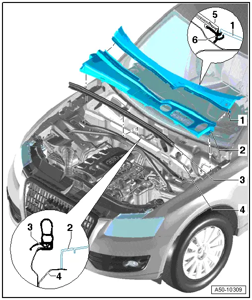
1 - Cowl Panel Trim
- The wiper arm is removed.
- The left, center and right auxiliary covers are removed.
- Remove the clamps -3-.
 Note
Note
For easier removal/installation, spray windshield frame with soapy water.
- Pull the cowl panel straight off the frame starting from the window edge.
 Caution
Risk of window breaking during installation
When installing, do not hit the cowl trim.
Carefully press cowl trim in sideways, beginning in the frame.
2 - Plenum Chamber Cover
- Remove the front clip first when removing.
- Lift the front cover and remove it from the plenum chamber cover.
3 - Seal
- Remove from the body flange toward the rear starting on the side.
4 - Plenum Chamber Bulkhead
5 - Windshield
6 - Frame
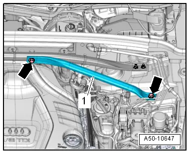
Tower Brace Reinforcement, Removing and Installing
Removing
- Remove the bolts -arrows-.
- Remove reinforcement -1-.
Installing
Install in reverse order of removal.
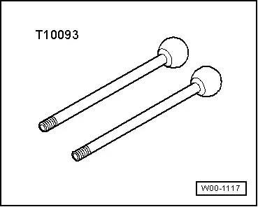
Special Tools
Special tools and workshop equipment required
- Guide Pins -T10093-
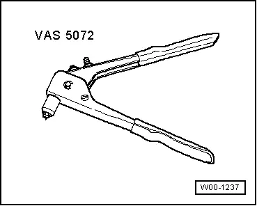
- Pop Rivet Pliers -VAS5072-
- Drill
- Pop rivets. Refer to the Parts Catalog.