Audi Q5: Brake Rotor, Replacing, Brake 1LV and 1ZK, SQ5
Special tools and workshop equipment required
- Torque Wrench 1331 5-50Nm -VAG1331-
- Torque Wrench 1332 40-200Nm -VAG1332-
Removing
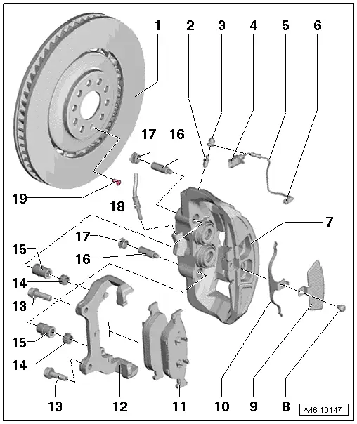
- Remove the bolt -19-.
- Remove the brake rotor.
Installing
 Note
Note
- Pay attention the arrow on the brake rotor showing the direction of travel and to the left and right installed location when installing the brake rotors.
- Use new bolts. Refer to Parts Catalog.
- Clean the brake rotor and the wheel hub before installing the brake rotor.
- Place the brake rotor on the hub.
 Note
Note
Do not tilt the brake rotor when mounting it on the wheel hub.
- Install and tighten the bolt -19-
 WARNING
There is the risk of an accident.
- Before moving the vehicle, press the brake pedal firmly several times to seat the brake pads correctly in their operating position.
- Make sure the brakes are working correctly before driving the vehicle.
Brake Shield, Removing and Installing
 Note
Note
Removal and installation of the brake 1LV is illustrated provisionally.
Removing
- Remove the brake rotor. Refer to → Chapter "Brake Rotor, Removing and Installing".
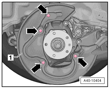
- Remove the cover plate screws -arrows-.
- Remove cover plate -1-.
Installing
- Mount the cover plate -1-.
- Install the bolts -arrows- and tighten them.
- Install the brake rotor. Refer to → Chapter "Brake Rotor, Removing and Installing".