Audi Q5: Backrest Adjustment Motor, Removing and Installing
Special tools and workshop equipment required
- Liquid Locking Fluid -D 000 600 A2-
Removing
 WARNING
- Follow all Safety Precautions when working with pyrotechnic components. Refer to → Chapter "Pyrotechnic Components Safety Precautions".
- Before handling airbag units (for example, disconnecting electrical connector), the person handling it must "discharge static electricity". This can be done by touching the door striker, for example.
- Remove the front seat. Refer to → Chapter "Front Seat, Removing and Installing".
- Attach the front seat to the Engine/Transmission Holder - Seat Repair Fixture -VAS6136-. Refer to → Chapter "Front Seat, Mounting on Fixture for Seat Repair".
- Remove the seat side sill panel trim. Refer to → Chapter "Sill Side Trim, Removing and Installing, Standard/Sport Manual Seats".
- Remove the Seat side trim on the tunnel side. Refer to → Chapter "Trim, Removing and Installing, Tunnel-Side".
- Remove the backrest cover. Refer to → Chapter "Backrest Cover, Removing and Installing".
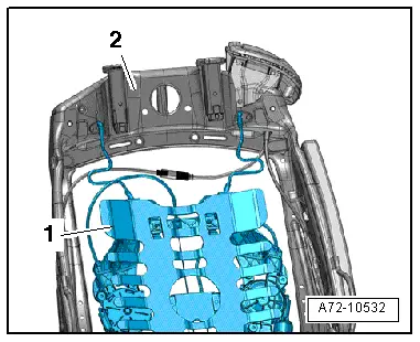
- Mark the angle adjustment of the left and right backrest mounting brackets on the seat as follows:
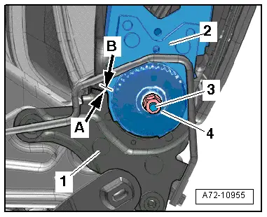
- Make a permanent mark (line) -arrow B- on the backrest frame -2- right at the front edge -arrow A- of the anchor -1-.
 Caution
Do not damage the surface of the anchor when marking it by scratching or denting it.
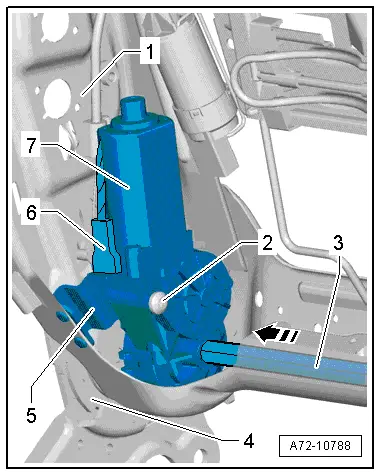
- Remove the nut -4- from the shaft -3-.

- Remove the cover from the backrest near the backrest hinge. Refer to → Chapter "Backrest Cover and Upholstery, Removing and Installing, Standard, Comfort, Sport Seat".
- Remove the shaft -3- from the backrest frame -1- in the direction of the -arrow-.
- Disconnect the connector -6- from the backrest adjustment motor -7-.
- Remove the screw -2- and remove the backrest adjustment motor from the bracket -5- while pushing the lumbar support motor slightly forward.
Installing
 WARNING
- Follow all Safety Precautions when working with pyrotechnic components. Refer to → Chapter "Pyrotechnic Components Safety Precautions".
- Before handling airbag units (for example, connecting the electrical connector), the person handling it must "discharge static electricity". This can be done by touching the door striker, for example.
- Clean the thread on the shaft -3- with a thread tap.
- Check the position of the backrest frame -2- and the anchor -1- on the left and right side.
- The left and right backrest frames must be in the position marked before removal -A and B arrows -.
- If the left and right backrest frames are not in the position marked before removal, correct their position accordingly.
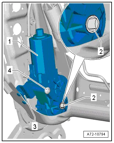
- Position the backrest adjustment motor -1- on the bracket -3-.
- Replace the bolt -4-, coat with Liquid Locking Fluid -D 000 600 A2- and tighten only hand-tight.
- It must still be possible to move the backrest adjustment motor.
- First slide the shaft through the anchor (tunnel side) as far as the stop -2- in the backrest adjustment motor.
- Check whether the profile of the inserted shaft and mount -2- in the backrest adjustment motor align.
- If the shaft profile and the mount in the backrest adjustment motor align:
- Slide the shaft through backrest adjustment motor and backrest frame.
- If the shaft profile and the mount in the backrest adjustment motor do not align:
- Connect an external power source (12 Volt) to the backrest adjustment motor -1-.
- Rotate mount -2- until it aligns with the shaft profile.
- Slide the shaft through backrest adjustment motor and backrest frame.
- Apply Locking Compound Fluid -D 000 600 A2- to the shaft threaded piece.

- Install the new nut -4- on the shaft -3- and tighten it.

- Bolt the backrest adjustment motor on the bracket -3- and tighten it to the tightening specification.
Install in reverse order of removal. Note the following:
 Note
Note
Make sure the connectors are installed correctly and are secure.
 WARNING
Ignition must be on when connecting battery. If pyrotechnic components (for example, airbag, belt tensioner) are not repaired correctly, they may deploy unintentionally after connecting battery. There must not be anyone inside the vehicle when connecting the battery.
 DANGER!
When working on vehicles with the ignition already switched on or that are ready to drive there is a danger of the engine starting unexpectedly and of being poisoned by gas in enclosed areas. Risk of body parts and/or clothing being clamped or pulled.
Perform the following before switching on the ignition:
- Move the selector lever into P.
- Activate the parking brake
- Turn off the ignition.
- Open the hood
- Connect Battery Charger -VAS5095A- to the battery jump start terminal.
- Turn on the ignition.
- Connect the battery ground cable with the ignition turned on. Refer to → Electrical Equipment; Rep. Gr.27; Battery; Battery, Disconnecting and Connecting.
 Note
Note
If the Airbag Indicator Lamp -K75- indicates a fault, check the DTC memory, erase it and check it again. Refer to Vehicle Diagnostic Tester.
Lumbar Support Adjustment Motors -V125-/-V126-/-V129-/-V130-, Removing and Installing
Special tools and workshop equipment required
- Pop Rivet Pliers -VAG1753B-
- Drill
- Protective eyewear
Removing
 WARNING
- Follow all Safety Precautions when working with pyrotechnic components. Refer to → Chapter "Pyrotechnic Components Safety Precautions".
- Before handling pyrotechnic components (for example, disconnecting the connector), the person handling it must "discharge static electricity". This can be done by touching the door striker, for example.
- Turn on the ignition.
- Disconnect the battery ground cable with the ignition turned on. Refer to → Electrical Equipment; Rep. Gr.27; Battery; Battery, Disconnecting and Connecting.
- Remove the front seat. Refer to → Chapter "Front Seat, Removing and Installing".
- Attach the front seat to the Engine/Transmission Holder - Seat Repair Fixture -VAS6136-. Refer to → Chapter "Front Seat, Mounting on Fixture for Seat Repair".
- Remove the backrest cover. Refer to → Chapter "Backrest Cover, Removing and Installing".
- Remove the headrests. Refer to → Chapter "Headrest, Removing and Installing".
- Remove cover with upholstery. Refer to → Chapter "Backrest Cover and Upholstery, Removing and Installing, Standard, Comfort, Sport Seat".
 Note
Note
Lay plastic film between the seat pan cover and the backrest frame to protect against metal shavings.
 WARNING
Danger of eye injury.
Wear protective eyewear.
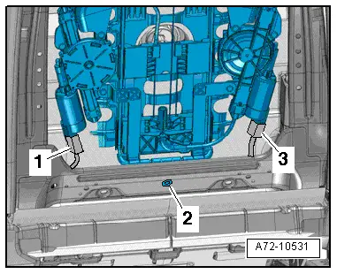
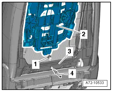
- Drill out rivet -2-.
- Disconnect electrical harness connectors -1- and -3- at the lumbar support curvature and height adjustment motors.
- Free up the electrical wiring harness at the four-way lumbar support -1-.
- Disengage and remove the 4-way lumbar support on the backrest frame -2-.
Installing
- Engage four-way lumbar support -1- on the backrest frame -2-.
- Before securing rivet -4-, a plastic washer -1- must be placed between lumbar support -2- and backrest frame -3-.
- Rivet the four-way lumbar support frame -2- with the backrest frame -3-.
 WARNING
- Follow all Safety Precautions when working with pyrotechnic components. Refer to → Chapter "Pyrotechnic Components Safety Precautions".
- Before handling pyrotechnic components (for example, connecting the connector), the person handling it must "discharge static electricity". This can be done by touching the door striker, for example.
Install in reverse order of removal. Note the following:
 Note
Note
Make sure the connectors are installed correctly and are secure.
 WARNING
Ignition must be on when connecting battery. If pyrotechnic components (for example, airbag, belt tensioner) are not repaired correctly, they may deploy unintentionally after connecting battery. There must not be anyone inside the vehicle when connecting the battery.
 DANGER!
When working on vehicles with the ignition already switched on or that are ready to drive there is a danger of the engine starting unexpectedly and of being poisoned by gas in enclosed areas. Risk of body parts and/or clothing being clamped or pulled.
Perform the following before switching on the ignition:
- Move the selector lever into P.
- Activate the parking brake
- Turn off the ignition.
- Open the hood
- Connect Battery Charger -VAS5095A- to the battery jump start terminal.
- Turn on the ignition.
- Connect the battery ground cable with the ignition turned on. Refer to → Electrical Equipment; Rep. Gr.27; Battery; Battery, Disconnecting and Connecting.
 Note
Note
If the Airbag Indicator Lamp -K75- indicates a fault, check the DTC memory, erase it and check it again. Refer to Vehicle Diagnostic Tester.

