Audi Q5: Vacuum System
Overview - Electric Vacuum Pump
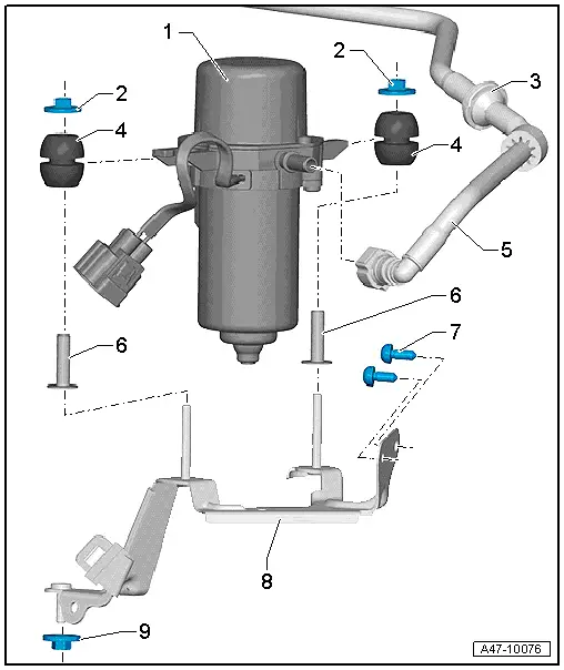
1 - Brake System Vacuum Pump -V192-
- Can be checked in the "Guided Fault Finding" using the Vehicle Diagnostic Tester
2 - Nut
- 9 Nm
3 - Check Valve
4 - Adjusting Buffer
5 - Vacuum Hose
6 - Sleeve
7 - Bolt
- 9 Nm
8 - Bracket
9 - Nut
- 8 Nm
 Note
Note
- The Brake Booster Pressure Sensor -G294- is installed on the brake booster.
- Removing and Installing. Refer to → Chapter "Brake Booster Pressure Sensor, Removing and Installing".
Overview - Vacuum Pump
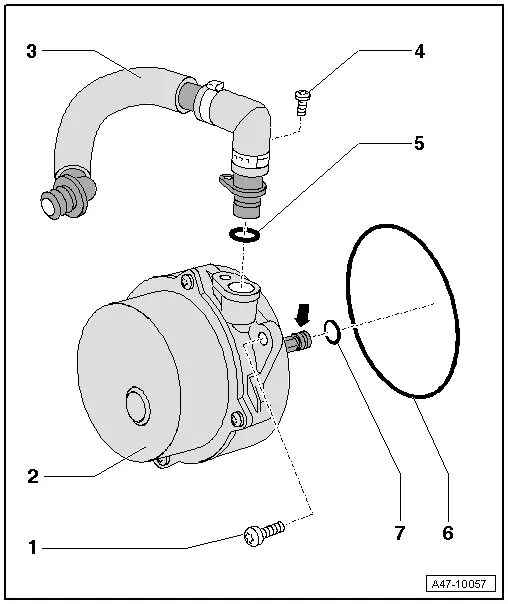
1 - Torx 30 Bolt (Quantity: 2)
- 9 Nm
- remove to remove the pump.
 Note
Note
The pump is not designed to be disassembled.
2 - Vacuum Pump
3 - Vacuum Hose
- Secure with hose clamp appropriate to model. Refer to Parts Catalog.
4 - Bolt
- 5 Nm
 Note
Note
Installing the bolt depends on the model.
Alternatively, secure the vacuum hose with the hose clamp for the vehicle version. Refer to Parts Catalog.
5 - O-Ring
- Replace
 Note
Note
Installation of the O-ring depends on the model.
6 - O-Ring
- Replace
 Note
Note
Installation of the O-ring depends on the model.
7 - O-Ring
- Replace
 Note
Note
Installation of the O-ring depends on the model.
Check Valve, Checking
 Note
Note
- The check valve is tightly installed in the vacuum hose.
- To check it, the vacuum hose must be removed.
Valve must allow air to flow in direction of -arrow-.
Valve must remain closed in opposite direction.
Observe correct installation position.
The flow direction arrow faces the vacuum pump.
Brake Booster Pressure Sensor, Removing and Installing
 Note
Note
The Brake Booster Pressure Sensor -G294- is installed inside the plenum chamber in front of the brake booster.
Removing
- Remove the plenum chamber cover. Refer to → Body Exterior; Rep. Gr.50; Bulkhead; Plenum Chamber Cover, Removing and Installing.
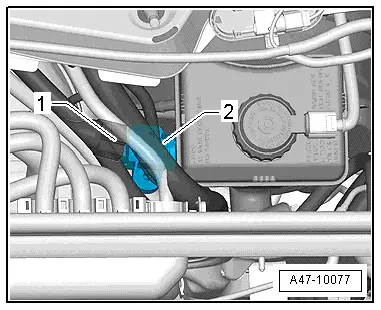
- Disconnect the connector -1-.
- Carefully pry the Brake Booster Pressure Sensor -G294- down and remove it.
Installing
Install in reverse order of removal.
- Install plenum chamber cover. Refer to → Body Exterior; Rep. Gr.50; Bulkhead; Plenum Chamber Cover, Removing and Installing.


