Audi Q5: Traffic Data Antenna, Removing and Installing
- Turn off the ignition and all electrical consumers and remove the ignition key.
 WARNING
Danger of unintended engine ignition
Turn off the ignition and remove the ignition key from the vehicle interior for all work performed on the high voltage vehicle.
Removing
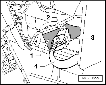
The Traffic Data Antenna -R173- connectors are located behind the Front Interior Lamp -W1-.
- Remove the Front Interior Lamp - W1-. Refer to → Electrical Equipment; Rep. Gr.96; Controls; Front Interior Lamp/Reading Lamp, Removing and Installing.
The connectors on the Front Interior Lamp -W1--3- do not need to be loosened.
- Loosen the foam sheathing -1-.
- Release the connectors -2- and -3- and disconnect them.
- Slide the line -4- toward the Traffic Data Antenna -R173- on the windshield.
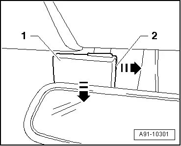
Traffic Data Antenna -R173- removal:
- Remove expanding clip -2- in direction of -arrow- with a small screwdriver.
- Remove Traffic Data Antenna -R173--1- downward in the direction of the -arrow- from the windshield.
Installing
- Install in reverse order of removal.
Tightening specifications and installation instructions can be found in the Component Location Overview. Refer to → Chapter "Navigation System Component Location Overview, Japan".
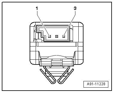
Connector Assignments
Left Antenna Module -R108-
1 - Window antenna connection (Digital Radio Antenna -R183-)
2 - DAB connection to the Radio -R-
3 - Not Assigned

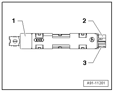
Antenna Amplifier -R24- (CAN)
1 - Window Antenna Connection (Radio Antenna 2 -R93-/Central Locking and Anti-Theft Alarm System Antenna -R47-)
2 - Connection FM2, to the Radio -R-
3 - CLS connection to Comfort System Central Control Module -J393-

Connectors, window antennas
1 - Radio Antenna 2 -R93- (FM2)/Central Locking and Anti-Theft Alarm System Antenna -R47- (CLS)
2 - Diag. Bridge to pin 3
3 - Diag. Bridge to pin 2

Antenna Amplifier -R24- (MMI)
1 - Window Antenna Connection (Antenna -R11-/Central Locking and Anti-Theft Alarm System Antenna -R47-)
2 - Connection FM2, to the Radio -R-
3 - CLS connection to Comfort System Central Control Module -J393-

Connectors, window antennas
1 - Antenna -R11- (FM2)/Central Locking and Anti-Theft Alarm System Antenna -R47- (CLS)
2 - Diag. Bridge to pin 3
3 - Diag. Bridge to pin 2

Antenna Amplifier 3 -R112- (CAN)
1 - Antenna Connections in Rear Spoiler (Antenna -R11-)
2 - AM/FM1 Connection to the Radio -R-
3 - Not Assigned

Connectors, antennas in the rear spoiler
1 - Antenna -R11- (AM)
2 - Antenna -R11- (FM1)/Diag. Bridge to pin 3
3 - Diag. Bridge to pin 2
Antenna Amplifier 3 -R112- (MMI)
1 - Antenna Connections in Rear Spoiler (Radio Antenna 2 --/TV Antenna 1 -R55-)
2 - AM/FM1 Connection to the Radio -R-
3 - TV1 connection to the TV Tuner -R78-

Connectors, antennas in the rear spoiler
1 - Radio Antenna 2 -R93- (AM/FM1)
2 - TV Antenna 1 -R55- (TV1)/Diag Bridge to pin 3
3 - Diag. Bridge to pin 2

Antenna Amplifier 4 -R113-, MMI
1 - TV Antenna 2 -R56- (TV2)/TV Antenna 3 -R57- (TV3)
2 - TV3 connection to the TV Tuner -R78-
3 - TV2 connection to the TV Tuner -R78-
Connectors, window antennas
1 - TV Antenna 3 -R57-
2 - TV Antenna 2 -R56-/Diag Bridge to pin 3
3 - Diag. Bridge to pin 2


