Audi Q5: Refrigerant Circuit
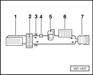
Refrigerant Circuit with Expansion Valve and Evaporator
The following illustration shows only the principle of a refrigerant circuit, the design of the refrigerant circuit in the respective vehicle can be found in the vehicle-specific repair manual. Refer to → Heating, Ventilation and Air Conditioning; Rep. Gr.87; Refrigerant Circuit; System Overview - Refrigerant Circuit.
1 - Evaporator
2 - Expansion Valve
3 - Valve for extracting, filling and measuring
4 - Sight glass (not installed in R134a circuits)
5 - Receiver/dryer with dryer
6 - Condenser
7 - A/C Compressor

 Note
Note
Arrows point in direction of refrigerant flow.
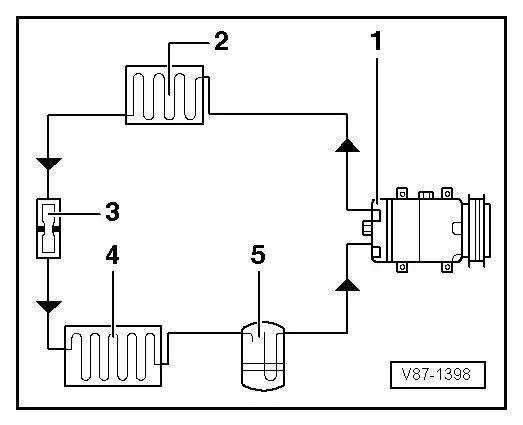
Refrigerant Circuit with Restrictor and Reservoir
The following illustration shows only the principle of a refrigerant circuit, the design of the refrigerant circuit in the respective vehicle can be found in the vehicle-specific repair manual. Refer to → Heating, Ventilation and Air Conditioning; Rep. Gr.87; Refrigerant Circuit; System Overview - Refrigerant Circuit.
1 - A/C Compressor
2 - Condenser
3 - Restrictor
4 - Evaporator
5 - Reservoir

 Note
Note
Arrows point in direction of refrigerant flow.
Refrigerant Circuit with an Electrically Driven A/C Compressor (with and without Battery Cooling Module)
Vehicles with a high-voltage system (hybrid vehicles)
Extremely Dangerous Due to High-Voltage
The high-voltage system is under high-voltage. Death or serious bodily injury by electric shock.
- Individuals with electronic/medical life- and health sustaining machines in or on their person cannot perform any work on high-voltage systems. Life- and health sustaining machines are for example pain killer pumps, implanted defibrillators, pacemakers, insulin pumps, and hearing aids.
- Have the high-voltage system de-energized by a qualified person.
There is a Risk of Injury from the Engine Starting Unexpectedly
On electric - hybrid vehicles an active ready mode is difficult to identify. Parts of the body can be clamped or pulled.
- Turn off the ignition.
- Place the ignition key outside of the vehicle interior.
Risk of Damaging the High-Voltage Cables
Misuse can damage the insulation of high-voltage cables or high-voltage connectors.
- Never support objects on the high-voltage cables and the high-voltage connectors.
- Never support tools on the high-voltage cables and the high-voltage connectors.
- Never sharply bend or kink the high-voltage cables.
- When connecting pay attention to the coding of the high-voltage connectors.
- For all procedures on vehicles with high-voltage system pay attention to the additional warning message for these vehicles. Refer to → Chapter "Warnings when Working on Vehicles with High Voltage System".
- If procedures are necessary near components of the high-voltage system "perform a visual inspection of the damage of the high-voltage components and lines". Refer to → Chapter "Performing a Visual Inspection of Damage to High Voltage Components and Cables".
- If work on the components of the high-voltage system is necessity, de-energize the high-voltage system. Refer to → Rep. Gr.93; High-Voltage System, De-Energizing or → Electrical Equipment; Rep. Gr.93; High-Voltage System, De-Energizing.
 Note
Note
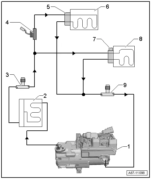
The following illustration shows a refrigerant circuit as an example, as it is installed in an Audi Q5 hybrid, for the design of the refrigerant circuit in the respective vehicle refer to the vehicle-specific repair manual. Refer to → Heating, Ventilation and Air Conditioning; Rep. Gr.87; Refrigerant Circuit; System Overview - Refrigerant Circuit.
-Arrows- point in direction of refrigerant flow.

1 - Electrically-Driven A/C Compressor
- With A/C Compressor Control Module -J842- and Electrical A/C Compressor -V470-
2 - Condenser
- With receiver/dryer and dryer cartridge
3 - Service Connection, HP side
4 - Hybrid Battery Refrigerant Shut-Off Valve 1 -N516-
- Only for vehicles with a battery cooling module for the Hybrid Battery Unit -AX1-.
 Note
Note
The Hybrid Battery Refrigerant Shut-Off Valve 1 -N516- is activated, for example, if it is necessary to cool the battery and no cooling is desired in the passenger compartment (open without activation).
5 - Expansion Valve
- On the evaporator in the A/C system
6 - Evaporator
- Evaporator in the A/C System
7 - Expansion Valve with Hybrid Battery Refrigerant Shut-Off Valve 2 -N517-
- On the evaporator in the battery cooling module
- Only for vehicles with a battery cooling module for the Hybrid Battery Unit -AX1-.
 Note
Note
The Hybrid Battery Refrigerant Shut-Off Valve 2 -N517- is activated if it is necessary to cool the battery (closed without activation).
8 - Evaporator
- Evaporator in the battery cooling module
- Only for vehicles with a battery cooling module for the Hybrid Battery Unit -AX1-.
9 - Service Connection, LP Side

