Audi Q5: Rearview Camera -R189-, Calibrating
- Setup requirements.
- Connect the Vehicle Diagnostic Tester.
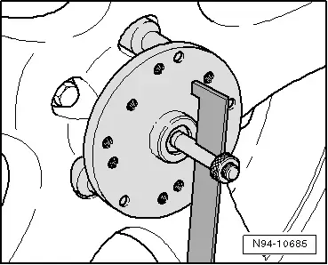
Calibration Tool - Wheel Center Mountings -VAS6350/1- installing:
- Check which hole circle the rims have.
- Mount the Calibration Tool - Wheel Center Mountings -VAS6350/1- appropriately.
- To do so, attach three wheel bolt adapters in the bolt circle to each Calibration Tool - Wheel Center Mountings -VAS6350/1-.
- Attach paddles to both Calibration Tool - Wheel Center Mountings -VAS6350/1- and secure them with clamping screw.
- Place the Wheel Center Mountings -VAS6350/1- onto the wheel bolts on the rear wheels.
The Calibration Tool - Wheel Center Mountings -VAS6350/1- are positioned by the "O rings" in the adapters and held in place.
 Note
Note
Attach the Calibration Tool - Wheel Center Mountings -VAS6350/1- onto the wheels so that any installed "anti-theft" wheel mounting bolts are not connected to the Calibration Tool - Wheel Center Mountings -VAS6350/1-.
- Adjust paddle with aid of clamping screws so that they move freely just above the floor. Make sure the paddles move easily.
- Install and align the Calibration Tool -VAS6350-. Refer to → Chapter "Calibration Tool -VAS6350-, Installing and Aligning".
Distance measurement:
- Switch on the Calibration Tool - Spacing Laser -VAS6350/2-.
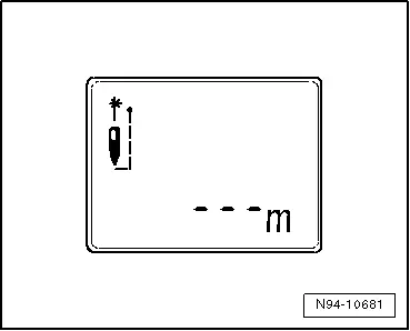
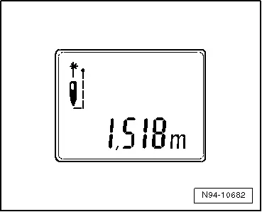
The following display appears:
- Hold the Calibration Tool - Spacing Laser -VAS6350/2--2- flush in the bracket on one side of the calibration board. The Calibration Tool - Spacing Laser -VAS6350/2--2- must sit securely in the bracket.
- Press the measuring button briefly.
The laser turns on.
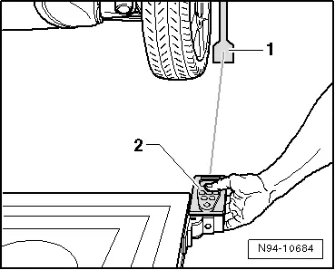
- Make sure that the laser beam from Calibration Tool - Spacing Laser -VAS6350/2--2- hits on the lower, enlarged part of paddle -1-.
If this is not the case, correct the paddles accordingly using clamping screws on the Calibration Tool - Wheel Center Mountings -VAS6350/1-.
- Use one hand to secure the Calibration Tool - Spacing Laser -VAS6350/2- in the bracket on the Calibration Unit -VAS6350A- while the laser beam is visible on the paddle.
- Press the measuring button briefly for the distance measurement.
Display readout
- Note the value read off.
- Repeat measuring procedure in the same manner for the other rear wheel on the other side of the Calibration Unit -VAS6350A-.
The distance value must be the same on both sides.
If values are not identical:
- Align the Calibration Unit -VAS6350A- long enough so that both sides are identical.
Pay attention when aligning the Calibration Unit -VAS6350A-, that the Calibration Tool - Linear Laser -VAS6350/3- from the Calibration Unit -VAS6350A- strikes the center of the Audi rings and the indicator of the level remains centered. If necessary, make further corrections.
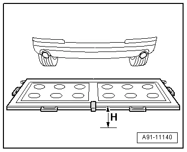
Dimension measurement -H-:
- Measure the height of the Calibration Unit -VAS6350A-, dimension -H- (top edge platform - floor).
Enter the height and distance dimensions into the Vehicle Diagnostic Tester in "millimeters".
Performing calibration
Vehicle Diagnostic Tester is attached.
- Select the Diagnostic mode and start the diagnostics.
- Select the tab test plan.
- Select select individual tests and choose the following sequence.
- Body
- Electrical Equipment
- 01 - OBD-capable systems
- 6C - rearview camera system/J772
- 6C - rearview camera system control module, functions
- 6C - Calibration, (Repair Group 91)
From here the Vehicle Diagnostic Tester advances the calibration procedure forward.
 WARNING
Make sure light does not reflect off the calibration platform.
Reflections affect the Rearview Camera -R189- and may make it impossible to perform the calibration.
Rearview Camera System Control Module -J772-, Removing and Installing
The Rearview Camera System Control Module -J772- is located behind the left luggage compartment side trim panel.
- If replacing the control module, select the "Replace Control Module" function on the Vehicle Diagnostic Tester.
Use Vehicle Diagnostic Tester.
- Turn off the ignition and all electrical consumers and remove the ignition key.
 WARNING
Danger of unintended engine ignition
Turn off the ignition and remove the ignition key from the vehicle interior for all work performed on the high voltage vehicle.
Removing
- Remove the cover from the left luggage compartment side trim panel.
- Remove the bracket with the Radio -R- and move it into the luggage compartment. Refer to → Chapter "Radio -R-, Removing and Installing, MMI".
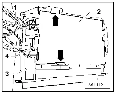
The Rearview Camera System Control Module -J772--2- is clipped into the bracket -3-.
- Disconnect the connectors -1- and -4- from the Rearview Camera System Control Module -J772--2-.
- Push the tabs -arrows- outward and remove the Rearview Camera System Control Module -J772--2- from the bracket -3-.
Installing
- Install in reverse order of removal.
- Install the bracket with the Radio -R-. Refer to → Chapter "Radio -R-, Removing and Installing, MMI".
- Perform the calibration. Refer to → Chapter "Rearview Camera System, Calibrating".
Tightening specifications and installation instructions can be found in the Component Location Overview. Refer to → Chapter "Component Location Overview - Rearview Camera System".
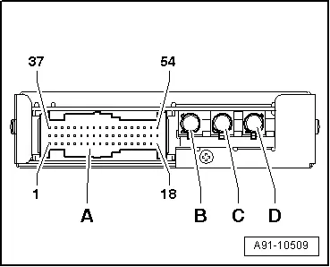
Rearview Camera System Control Module -J772- Connectors
Rearview Camera System Control Module -J772-
A - Black 54-Pin Connector
B - Not Assigned
- CVBS Output (Green) to Information Electronics Control Module 1 -J794-, Japan
C - CVBS Output (Green) to Information Electronics Control Module 1 -J794-
- CVBS Input (Gray) from Rear View Camera -R189-, Japan
D - CVBS Input (Gray) from Rear View Camera -R189-
- CVBS Input (Purple) from Camera in Exterior Rearview Mirror -R223-, Japan

 Note
Note
Unlisted connector terminals are not assigned.
A - Black 54-pin connector
39 - Convenience CAN Bus low
40 - Convenience CAN Bus high
43 - Terminal 30
44 - Terminal 31
47 - Terminal 31 to the Rearview Camera -R189-
48 - Rearview Camera -R189- power supply
49 - Terminal 31 to the Camera in Exterior Rearview Mirror -R223-, Japan
50 - Camera in Exterior Rearview Mirror -R223- Power Supply, Japan
52 - Exterior Rearview Mirror Camera Button -E697-, Japan
53 - Exterior Rearview Mirror Camera Button -E697-, Japan