Audi Q5: Radio/Navigation System Frame, Removing and Installing
Removing
- Remove the center instrument panel vent. Refer to → Chapter "Instrument Panel Vent, Removing and Installing, Center Instrument Panel Vent".
- Remove the radio. Refer to → Communication; Rep. Gr.91; Radio; Radio, Removing and Installing.
- Remove the navigation system. Refer to → Communication; Rep. Gr.91; Infotainment System; Information Electronics Control Module 1 J794, Removing and Installing.
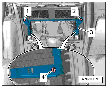
- Remove the bolts -1- and -2- on the front of the installation frame.
- Remove the side bolts -4-.
- Pull the installation frame -3- back and remove it.
Installing
Install in reverse order of removal.
Access/Start Authorization Switch Trim, Removing and Installing
Special tools and workshop equipment required
- Ignition Lock Pliers -VAS6339-
Removing
- Remove the center instrument panel vent. Refer to → Chapter "Instrument Panel Vent, Removing and Installing, Center Instrument Panel Vent".
- Insert the Ignition Lock Pliers -VAS6339- through the trim covers.
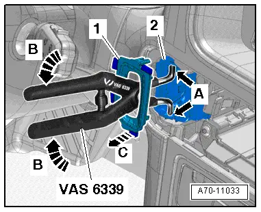
- Position the tips of the Ignition Lock Pliers -VAS6339- on both holes -A arrows- on the access/start authorization switch -E415--2-.
- Press the Ignition Lock Pliers -VAS6339- together -B arrows- to spread the tips of the pliers and release the trim retaining tabs.
- Hold the Ignition Lock Pliers -VAS6339- pressed with one hand and remove the trim -1- with the other hand -arrow C-.
 Note
Note
Only use the Ignition Lock Pliers -VAS6339-. Remove the trim by hand.
Installing
- Install the upper and lower trim on the switch until they audibly latch.
- Install the center instrument panel vents. Refer to → Chapter "Instrument Panel Vent, Removing and Installing, Center Instrument Panel Vent".
Instrument Panel, Removing and Installing
Removing
- Move the steering wheel as far down as possible.
- Move the seat all the way back and adjust the backrest to a 45º angle.
 WARNING
- Follow all Safety Precautions when working with pyrotechnic components. Refer to → Chapter "Pyrotechnic Components Safety Precautions".
- Follow the allocation of the airbag to the instrument panel. Refer to the → Electronic Parts Catalog (ETKA).
- Turn on the ignition.
- Disconnect the battery ground cable with the ignition turned on. Refer to → Electrical Equipment; Rep. Gr.27; Battery; Battery, Disconnecting and Connecting.
- Remove the instrument cluster gap cover. Refer to → Chapter "Instrument Cluster Gap Cover, Removing and Installing".
- Remove the instrument panel cover on the driver side. Refer to → Chapter "Driver Side Instrument Panel Cover, Removing and Installing".
- Remove the side instrument panel vent. Refer to → Chapter "Instrument Panel Vent, Removing and Installing, Side Instrument Panel Vent".
- Remove the MMI screen cover. Refer to → Chapter "MMI Screen Cover, Removing and Installing".
- Remove the MMI screen. Refer to → Communication; Rep. Gr.91; Infotainment System; Infotainment System Display, Removing and Installing.
- Remove the Instrument Cluster. Refer to → Electrical Equipment; Rep. Gr.90; Instrument Cluster; Overview - Instrument Cluster.
- Disconnect the connector to the Access/Start Authorization Switch. Refer to → Electrical Equipment; Rep. Gr.96; Controls; Access/Start Authorization Button E408, Removing and Installing.
- Remove the center instrument panel vent. Refer to → Chapter "Instrument Panel Vent, Removing and Installing, Center Instrument Panel Vent".
- Remove the radio. Refer to → Communication; Rep. Gr.91; Radio; Radio, Removing and Installing.
- Remove the navigation system. Refer to → Communication; Rep. Gr.91; Infotainment System; Information Electronics Control Module 1 J794, Removing and Installing.
- Remove the Climatronic Control Module -J255-. Refer to → Heating, Ventilation and Air Conditioning; Rep. Gr.87; Display and Control Head; Display and Control Head, Removing and Installing.
- Remove the Front Information Display Control Head Control Module -J523-. Refer to → Communication; Rep. Gr.91; Infotainment System; Component Location Overview - Infotainment System.
- Remove the center console. Refer to → Chapter "Center Console, Removing and Installing".
- Remove the glove compartment. Refer to → Chapter "Glove Compartment, Removing and Installing".
- Remove the Glove Compartment Mount. Refer to → Chapter "Glove Compartment Mount, Removing and Installing".
 WARNING
Before handling pyrotechnic components (for example, disconnecting the connector), the person handling it must "discharge static electricity". This can be done by touching the door striker, for example.
- Disconnect the passenger airbag electrical connector. Refer to → Chapter "Front Passenger Airbag Unit with Igniter, Removing and Installing".
- Versions with a speaker: Remove the Mid-Treble Speaker from the center of the instrument panel. Refer to → Communication; Rep. Gr.91; Sound System; Center Speaker, Removing and Installing.
- Remove the Sunlight Photo Sensor -G107-. Refer to → Heating, Ventilation and Air Conditioning; Rep. Gr.87; Additional Components for Control and Regulation; Sunlight Photo Sensor G107, Removing and Installing.
- Remove the A-pillar upper trim. Refer to → Chapter "A-Pillar Trim Panel, Removing and Installing".
- Versions with a speaker: Remove the side mid-treble speaker in the instrument panel. Refer to → Communication; Rep. Gr.91; Sound System; Component Location Overview - Sound System.
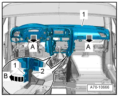
- Remove the top left and right instrument panel bolts -1- in the A-pillar area.
- Remove the bottom left and right instrument panel bolts -2-.
- Remove the left and right air duct bolts -arrows- on the instrument panel.
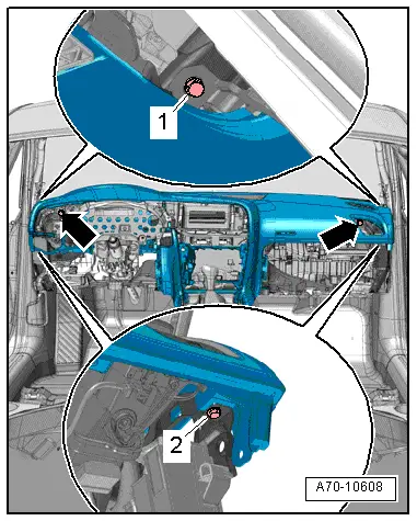
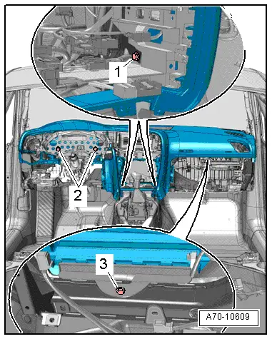
- Remove the instrument panel bolts -1- on the center of the instrument panel central tube.
- Remove the instrument panel bolts -2- on the right of the instrument panel central tube.
- Remove the instrument panel bolt -3- on the left of the instrument panel central tube.
 Note
Note
Two technicians are needed to remove the instrument panel.
- Disengage the instrument panel -1- at the bottom from the bracket -2- and remove it -arrow B-.
- Carefully pull the instrument panel back from the instrument panel central tube -A arrows-.
- Remove the instrument panel on the passenger side from the vehicle interior and lay it on a soft surface.
Installing
Install in reverse order of removal. Note the following:
 WARNING
Follow the allocation of the airbag to the instrument panel. Refer to the Parts Catalog.
- Set the instrument panel in place and guide the electrical harness connectors for Sunlight Photo Sensor -G107- and speaker through the openings in the instrument panel.
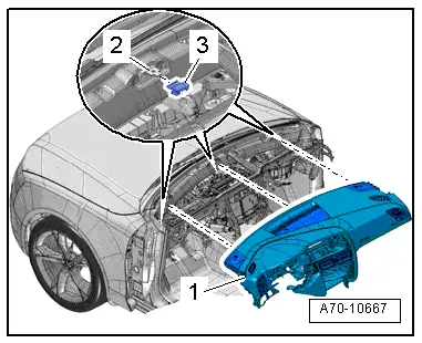
- Check if there is a rubber buffer -3- on the clamp -2- on the lower windshield frame.
- When sliding the instrument panel -1- on, make sure the clips engage in the box-shaped profiles on the bottom side of the instrument panel.
 WARNING
- Follow all Safety Precautions when working with pyrotechnic components. Refer to → Chapter "Pyrotechnic Components Safety Precautions".
- Before handling pyrotechnic components (for example, connecting the connector), the person handling it must "discharge static electricity". This can be done by touching the door striker, for example.
 Note
Note
Make sure the connectors are installed correctly and are secure.
- Align the instrument panel with the door trim panels and tighten the screws.
 WARNING
Ignition must be on when connecting battery. If pyrotechnic components (for example, airbag, belt tensioner) are not repaired correctly, they may deploy unintentionally after connecting battery. There must not be anyone inside the vehicle when connecting the battery.
 DANGER!
When working on vehicles with the ignition already switched on or that are ready to drive there is a danger of the engine starting unexpectedly and of being poisoned by gas in enclosed areas. Risk of body parts and/or clothing being clamped or pulled.
Perform the following before switching on the ignition:
- Move the selector lever into P.
- Activate the parking brake
- Turn off the ignition.
- Open the hood
- Connect Battery Charger -VAS5095A- to the battery jump start terminal.
- Turn on the ignition.
- Connect the battery ground cable with the ignition turned on. Refer to → Electrical Equipment; Rep. Gr.27; Battery; Battery, Disconnecting and Connecting.
 Note
Note
If the Airbag Indicator Lamp -K75- indicates a fault, check the DTC memory, erase it and check it again → Vehicle diagnostic tester.

