Audi Q5: Instrument Panel Central Tube, Removing and Installing
Removing
- Remove the instrument panel. Refer to → Chapter "Instrument Panel, Removing and Installing".
- Unbolt steering column from the central tube and lay it on the floor of the vehicle. Refer to → Suspension, Wheels, Steering; Rep. Gr.48; Steering Column; Steering Column, Removing and Installing.
- Disengage the left instrument panel central tube air ducts. Refer to → Heating, Ventilation and Air Conditioning; Rep. Gr.87; Air Guide; Overview - Air Routing and Air Distribution in Passenger Compartment.
- Remove the instrument panel vent air duct. Refer to → Heating, Ventilation and Air Conditioning; Rep. Gr.87; Air Guide; Overview - Air Routing and Air Distribution in Passenger Compartment.
- Remove the left Fuse Holder C -SC- and the right Fuse holder D -SD-from the instrument panel central tube. Refer to → Electrical Equipment; Rep. Gr.97; Relay Panels, Fuse Panels and E-Boxes; Overview - Relay Panels, Fuse Panels and E-Boxes.
- Remove the Data Bus on Board Diagnostic Interface -J533- and set aside. Refer to → Electrical Equipment; Rep. Gr.97; Control Modules; Data Bus On Board Diagnostic Interface J533, Removing and Installing.
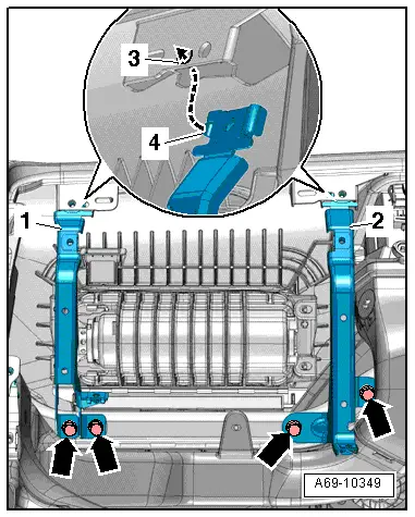
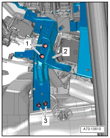
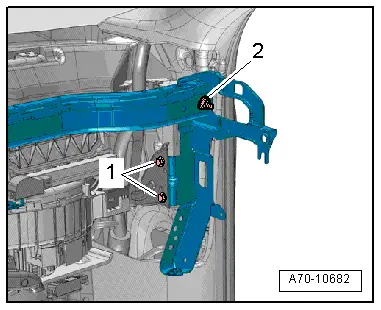
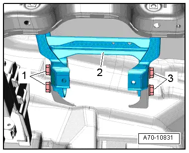
- Remove the bolts -1- on the left and right of the central tube support and remove the bracket -2-.
- Remove the left and right bolts -3- for the central tube support.
- Remove the A/C unit bolt -1- on the left and right of the central tube support.
- Remove the middle defroster vent air duct. Refer to → Heating, Ventilation and Air Conditioning; Rep. Gr.87; Air Guide; Overview - Air Routing and Air Distribution in Passenger Compartment.
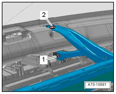
- Remove the A/C unit bolt -1- on the instrument panel central tube top brace.
- Remove the bolt -2- on the top brace on the instrument panel central tube.
- Remove the ground wire and left ground point from the tunnel wall and free them up.
- Disconnect the connectors on the accelerator pedal module and the brake light switch and free them up.
- Remove the front right sill panel trim. Refer to → Chapter "Sill Panel Strip, Removing and Installing, Front Sill Panel".
- Disconnect the connector at the connector station A on the right. Refer to → Electrical Equipment; Rep. Gr.97; Relay Panels, Fuse Panels and E-Boxes; Overview - Relay Panels, Fuse Panels and E-Boxes.
- Disconnect the electrical connector on the fresh air blower and free up the wires.
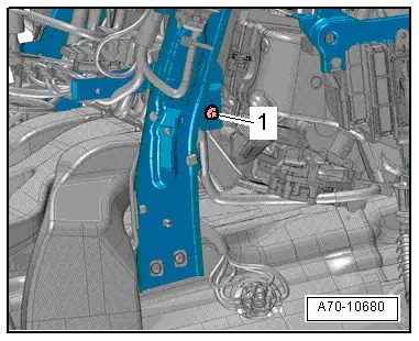
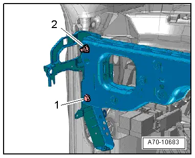
- Remove the air intake chamber bracket bolts -1- on the instrument panel central tube.
- Remove the nut -2-.
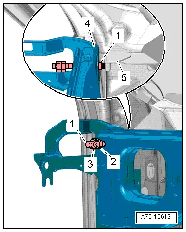
- Remove the bolt -1- and nut -2-.
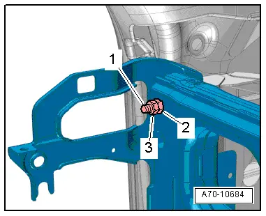
- Tighten the 2 nuts -2- and -3- on the threaded pin -1- on the driver side A-pillar and remove the threaded pin.
 Note
Note
Two technicians are needed to remove instrument panel central tube.
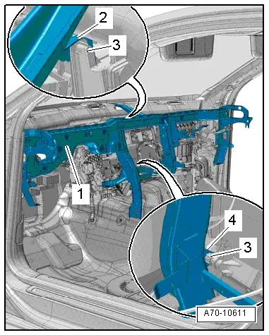
- Carefully pull the instrument panel central tube -1- up at the driver side while disengaging it from the A/C unit -3- and the upper -2- and lower -4- stop brackets.
- Remove the instrument panel central tube from the threaded pin on the passenger side A-pillar.
- Carefully tilt the top side of the instrument panel central tube back while pulling it up.
- Remove the instrument panel central tube from the vehicle interior.
Installing
- Carefully insert the instrument panel central tube -1- in the body.
- Engage the instrument panel central tube on the A/C unit -3- and on the upper -2- and lower -4- stop brackets.
- Align the instrument panel central tube -4- with the A-pillar.
- Tighten the two nuts -2- and -3- on threaded pin -1- and insert the threaded pin in mount -5- on the A-pillar on the driver side and tighten.
- The threaded pin must be installed all the way until the collar on the mount touches the A-pillar.
- Tighten the left and right instrument panel central tube bolts and nuts.
Install in reverse order of removal. Note the following:
- Install steering column. Refer to → Rep. Gr.48; Steering Column; Steering Column, Removing and Installing.
 WARNING
Ignition must be on when connecting battery. If pyrotechnic components (for example, airbag, belt tensioner) are not repaired correctly, they may deploy unintentionally after connecting battery. There must not be anyone inside the vehicle when connecting the battery.
 DANGER!
When working on vehicles with the ignition already switched on or that are ready to drive there is a danger of the engine starting unexpectedly and of being poisoned by gas in enclosed areas. Risk of body parts and/or clothing being clamped or pulled.
Perform the following before switching on the ignition:
- Move the selector lever into P.
- Activate the parking brake
- Turn off the ignition.
- Open the hood
- Connect Battery Charger -VAS5095A- to the battery jump start terminal.
- Turn on the ignition.
- Connect the battery ground cable with the ignition turned on. Refer to → Electrical Equipment; Rep. Gr.27; Battery; Battery, Disconnecting and Connecting.
 Note
Note
If the Airbag Indicator Lamp -K75- indicates a fault, check the DTC memory, erase it and check it again. Refer to Vehicle Diagnostic Tester.
Mounting Bracket, Removing and Installing
Removing
- Remove the left instrument panel vent air guide channel. Refer to → Heating, Ventilation and Air Conditioning; Rep. Gr.87; Air Guide; Overview - Air Routing and Air Distribution in Passenger Compartment.
- Remove the bolts -1- and -3- and remove the mounting bracket -2- downward.
 Note
Note
The removed steering column is shown in the illustration.
Installing
Install in reverse order of removal. Note the following:
- The mounting bracket can be correctly positioned only when the central tube is installed.
- Attach the steering column and mounting bracket to the central tube. Refer to → Suspension, Wheels, Steering; Rep. Gr.48; Steering Column; Steering Column, Removing and Installing first, and then tighten the mounting bracket screws -1- and -3- to the mount on the lower windshield frame.
Bumper, Removing and Installing
Removing
- Remove the instrument panel cover on the driver side. Refer to → Chapter "Driver Side Instrument Panel Cover, Removing and Installing".
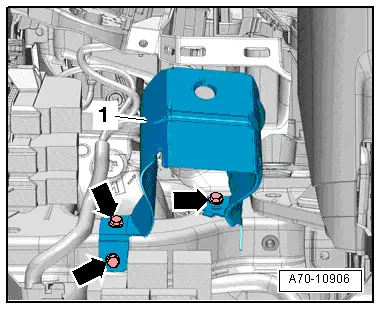
Left Shock Absorber:
- Remove the bolts -arrows-.
- Remove the left impact absorber -1- downward.
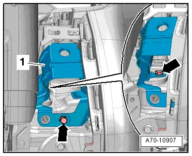
Right Shock Absorber:
- Remove the footwell vent on the driver side. Refer to → Heating, Ventilation and Air Conditioning; Rep. Gr.87; Air Guide; Overview - Air Routing and Air Distribution in Passenger Compartment.
- Remove the bolts -arrows-.
- Remove the right impact absorber -1- downward.
Installing
Install in reverse order of removal.
Glove Compartment Mount, Removing and Installing
Removing
- Remove the glove compartment. Refer to → Chapter "Glove Compartment, Removing and Installing".
- Remove the bolts -arrows-.
- Remove the left -1- and when installed, also the right -2- glove compartment brackets.
Installing
- Position the respective glove compartment brackets so that tab -4- engages in hole -3- in the instrument panel.
Install in reverse order of removal.