Audi Q5: Instrument Panel Component Location Overview
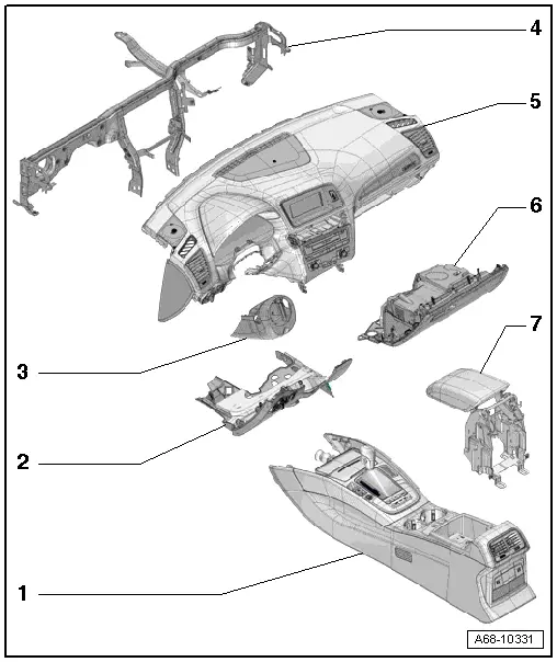
1 - Center Console
- Overview. Refer to → Chapter "Overview - Center Console".
2 - Driver Side Instrument Panel Cover
- Overview. Refer to → Chapter "Overview - Driver Side Instrument Panel Cover".
3 - Trim Panel
- For the steering column switch module
- Overview. Refer to → Chapter "Overview - Steering Column Trim Panel".
4 - Central Tube
- For the instrument panel
- Overview. Refer to → Chapter "Overview - Instrument Panel Central Tube".
5 - Instrument Panel
- Overview. Refer to → Chapter "Overview - Instrument Panel".
6 - Glove Compartment
- Overview. Refer to → Chapter "Overview - Glove Compartment".
7 - Front Center Armrest
- Equipment levels
- Overview. Refer to → Chapter "Overview - Front Center Armrest".
Overview - Instrument Panel
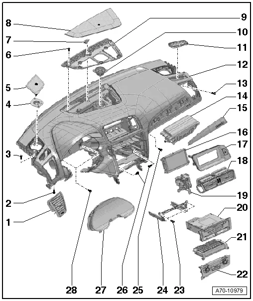
1 - Side Instrument Panel Vent
- Removing and installing. Refer to → Chapter "Instrument Panel Vent, Removing and Installing, Side Instrument Panel Vent".
2 - Bolt
- 3 Nm
- Quantity: 2
3 - Bolt
- 3 Nm
- Quantity: 2
4 - Mid-range Speaker
- Equipment levels
- Removing and installing. Refer to → Communication; Rep. Gr.91; Sound System; Front Midrange Speaker, Removing and Installing.
5 - Side Speaker Trim
- Equipment levels
- Removing and installing. Refer to → Chapter "Speaker Trim, Removing and Installing, Side Speaker Trim".
6 - Bolt
- 1.5 Nm
- Quantity: 6
7 - Sunlight Photo Sensor -G107-
- Removing and installing. Refer to → Heating, Ventilation and Air Conditioning; Rep. Gr.87; Additional Components for Control and Regulation; Sunlight Photo Sensor G107, Removing and Installing.
8 - Center Speaker Trim
- Equipment levels
- Removing and installing. Refer to → Chapter "Speaker Trim, Removing and Installing, Center Speaker".
9 - Upper Center Defroster Vent
- Removing and installing. Refer to → Chapter "Front Center Defroster Vent, Removing and Installing".
10 - Mid-range Speaker
- Equipment levels
- Removing and installing. Refer to → Communication; Rep. Gr.91; Sound System; Component Location Overview - Sound System.
11 - Upper Side Defroster Vent
12 - Instrument Panel
 WARNING
- Follow all Safety Precautions when working with pyrotechnic components. Refer to → Chapter "Pyrotechnic Components Safety Precautions".
- Follow the allocation of the airbag to the instrument panel. Refer to the → Electronic Parts Catalog (ETKA).
- Removing and installing. Refer to → Chapter "Instrument Panel, Removing and Installing".
13 - Bolt
- 3 Nm
- Quantity: 2
14 - Front Passenger Airbag
 WARNING
- Follow all Safety Precautions when working with pyrotechnic components. Refer to → Chapter "Pyrotechnic Components Safety Precautions".
- Follow the allocation of the airbag to the instrument panel. Refer to the → Electronic Parts Catalog (ETKA).
- Overview. Refer to → Chapter "Overview - Front Passenger Airbag".
- Locking and activating possible with key switch
- Removing and installing. Refer to → Chapter "Front Passenger Airbag Unit with Igniter, Removing and Installing".
15 - Trim Molding
- For the instrument panel
- Removing and installing. Refer to → Chapter "Instrument Panel Decorative Trim, Removing and Installing".
16 - MMI Screen
- Removing and Installing. Refer to → Communication; Rep. Gr.91; Infotainment System; Infotainment System Display, Removing and Installing.
17 - Cover
- for MMI screen
- Removing and installing. Refer to → Chapter "MMI Screen Cover, Removing and Installing".
18 - Center Instrument Panel Vent
- Removing and installing. Refer to → Chapter "Instrument Panel Vent, Removing and Installing, Center Instrument Panel Vent".
19 - Access/Start Authorization Switch -E415-
- Removing and Installing. Refer to → Electrical Equipment; Rep. Gr.94; Access/Start Authorization; Overview - Access/Start Authorization System.
- Trim, Removing and Installing. Refer to → Chapter "Access/Start Authorization Switch Trim, Removing and Installing".
20 - Radio/Navigation System
- Equipment levels
- Radio removing and installing. Refer to → Communication; Rep. Gr.91; Radio; Radio, Removing and Installing.
- Navigation system removing and installing. Refer to → Communication; Rep. Gr.91; Infotainment System; Information Electronics Control Module 1 J794, Removing and Installing.
21 - Front Information Display Control Head Module -J523-
- Removing and installing. Refer to → Communication; Rep. Gr.91; Infotainment System; Component Location Overview - Infotainment System.
22 - Climatronic Control Module -J255-
- Equipment levels
- Removing and installing. Refer to → Heating, Ventilation and Air Conditioning; Rep. Gr.87; Display and Control Head; Display and Control Head, Removing and Installing.
23 - Bolt
- 3 Nm
- Quantity: 4
24 - Installation Frame
- For the radio/navigation system
- Equipment levels
- Removing and installing. Refer to → Chapter "Radio/Navigation System Frame, Removing and Installing".
25 - Bolt
- 3 Nm
26 - Bolt
- 3 Nm
- Quantity: 2
27 - Instrument Cluster
- Removing and installing. Refer to → Electrical Equipment; Rep. Gr.90; Instrument Cluster; Overview - Instrument Cluster.
28 - Bolt
- 3 Nm
- Quantity: 2

