Audi Q5: Flange Input Shaft Ring, Replacing
Flange Input Shaft Ring, Replacing, 0BC
- The ring can only be replaced with the input shaft removed.
Special tools and workshop equipment required
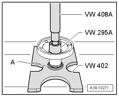
- Bearing/Bushing Installer - Multiple Use -VW295A-
- Press Plate -VW402-
- Press Piece - Rod -VW408A-
- Support Channels -VW457-
- -3-Separating device 12 to 75 mm, for example Puller - Kukko Quick Action Separating Tool - 12-75mm -17/1-
- Input shaft removed. Refer to → Chapter "Input Shaft Seal, Replacing, 0BC".
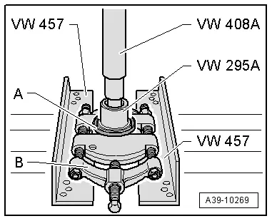
Remove the Ring -A- from the Flange/Driveshaft
B - Puller, for example, Puller - Kukko Quick Action Separating Tool - 12-75mm -Kukko 17/1-

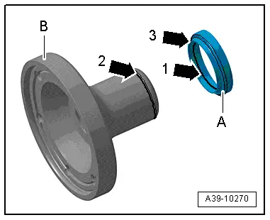
Installation Location of the Protective Ring -A- on the Flange/Driveshaft
- The ridge -arrow 1- on the protective ring -A- must fit into the groove -arrow 2- on the flange -B-. The smaller outer circumference -arrow 3- faces the flange.
Install the Protective Ring -A- onto the Flange/Driveshaft.
- The protective ring -A- must fit into the groove all around the flange. Refer to → Fig. "Installation Location of the Protective Ring -A- on the Flange/Driveshaft".

Flange Input Shaft Ring, Replacing, 0BD
- The ring can only be replaced with the input shaft removed.
Special tools and workshop equipment required
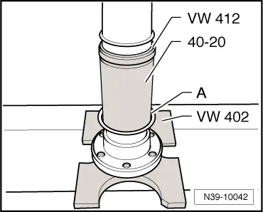
- Press Plate -VW402-
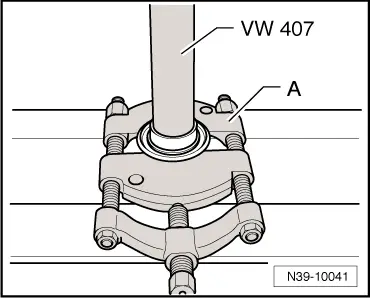
- Press Piece - Rod -VW407-
- Press Piece - Multiple Use -VW412-
- Bearing Installer - Multiple Use -40 - 20-
- Separating tool 22 to 75 mm, such as -17/1-
- Input shaft removed. Refer to → Chapter "Input Shaft Seal, Replacing, 0BD".
Press the Protective Ring off the Flange/Driveshaft
A - Separating Tool - 22-115mm, such as Puller - Kukko Quick Action Separating Tool - 22-115mm -17/2-
Install the Protective Ring -A- onto the Flange/Driveshaft
- Protective ring -A- installation position: the protective ring notch points upward to the Bearing Installer - Multiple Use -40 - 20-.
Flange Input Shaft Ring, Replacing, 0BE, 0BF
- The ring can only be replaced with the input shaft removed.
Special tools and workshop equipment required
- Bearing/Bushing Installer - Multiple Use -VW295A-
- Press Plate -VW402-
- Press Piece - Rod -VW408A-
- Support Channels -VW457-
- -3-Separating tool 22 to 75 mm, such as Puller - Kukko Quick Action Separating Tool - 12-75mm -17/1-
- Input shaft removed. 0BE (refer to → Chapter "Input Shaft Seal, Replacing, 0BE".) or 0BF (refer to → Chapter "Input Shaft Seal, Replacing, 0BF".)
Remove the Ring -A- from the Flange/Driveshaft
B - Separating Tool - 12-75mm, such as Puller - Kukko Quick Action Separating Tool - 12-75mm -17/1-
Installation Location of the Protective Ring -A- on the Flange/Driveshaft
- The ridge -arrow 1- on the protective ring -A- must fit into the groove -arrow 2- on the flange -B-. The smaller outer circumference -arrow 3- faces the flange.

Install the Protective Ring -A- onto the Flange/Driveshaft
- The protective ring -A- must fit into the groove all around the flange. Refer to → Fig. "Installation Location of the Protective Ring -A- on the Flange/Driveshaft".