Audi Q5: Rearview Camera System, Calibrating
Calibration Tool -VAS6350-, Installing and Aligning
Special tools and workshop equipment required
- Calibration Tool -VAS6350-
- Vehicle Diagnostic Tester
After performing service work on the vehicle, it may be necessary to calibrate the rearview camera system. In detail, this is the case after:
- Rearview Camera -R189- Removal and Installation
- Replacing Rearview Camera System Control Module -J772-
- Collision repairs on rear lid
- Axle alignment
- Rear Axle Repairs
Calibration Requirements
- The camera lens must be clean. Cleaning
- The vehicle must be standing on a firm and level surface.
- There must be sufficient open space around the vehicle.
- The parking brake must be set.
- The steering wheel must be in the 0 position and the wheels must be straight.
- All doors and the rear lid must be closed.
- No one should be in the vehicle.
- The vehicle must not be loaded (curb weight).
- Before each calibration: turn on the ignition.
The Calibration Tool -VAS6350- consists of the following parts:
- Calibration Tool - Wheel Center Mountings -VAS6350/1-
- Calibration Tool - Spacing Laser -VAS6350/2-
- Calibration Tool - Linear Laser -VAS6350/3-
Installed Calibration Tool -VAS6350- Overview
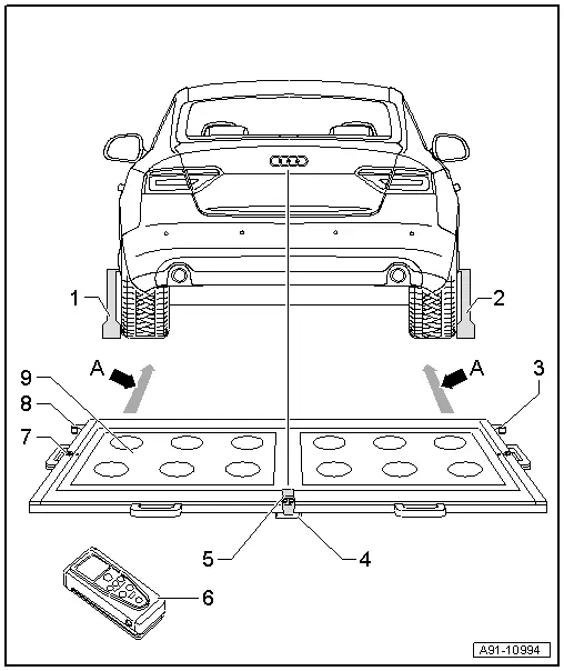
1 - Calibration Tool - Wheel Center Mountings -VAS6350/1-
2 - Calibration Tool - Wheel Center Mountings -VAS6350/1-
3 - Right angle bracket
- Calibration Tool - Spacing Laser -VAS6350/2- mount
4 - Plastic Foot
- Three on underside of calibration platform
- Adjustable for aligning horizontal position of calibration platform
5 - Calibration Tool - Linear Laser -VAS6350/3-
- On the calibration board
- Switching on and off. Refer to Operating Instructions.
6 - Calibration Tool - Spacing Laser -VAS6350/2-
- Notes on operation. Refer to the Operating Instructions.
7 - Level
- On the calibration board
- for checking the horizontal position
8 - Left angle bracket
- Calibration Tool - Spacing Laser -VAS6350/2- mount
9 - Calibration Board
- Between the mounts on the calibration board and the Calibration Tool - Wheel Center Mountings -VAS6350/1--dimension A- 1.47 m through 1.90 m
Calibration board alignment
- Position the calibration platform behind the vehicle at a distance of 1.47 m to 1.90 m to the rear wheels, see -dimension A- in the illustration.
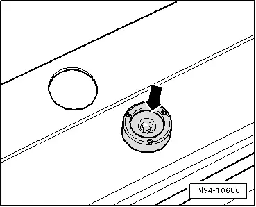
- Bring the Calibration Tool -VAS6350- into a horizontal position.
- Twist the plastic feet under the calibration board so that air bubble in level is located exactly in the center of the indicator -arrow-.
 WARNING
Make sure light does not reflect off the calibration platform.
Reflections affect the Rearview Camera -R189- and may make it impossible to perform the calibration.
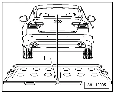
- Switch on the Calibration Tool - Linear Laser -VAS6350/3--1- on the calibration board and align the entire Calibration Tool -VAS6350A-, so that the laser beam points to the middle of the vehicle height above the Audi rings.
- Make sure the Audi rings are centered on the rear. Adjust the laser beam as needed.
Continue calibrating the Rearview Camera -R189-. Refer to → Chapter "Rearview Camera -R189-, Calibrating".