Audi Q5 Owners & Service Manuals

Audi Q5: Power meter overview

Applies to vehicles: with hybrid drive

The power meter shows the hybrid drive condition and the availability of the hybrid system.

Hybrid drive
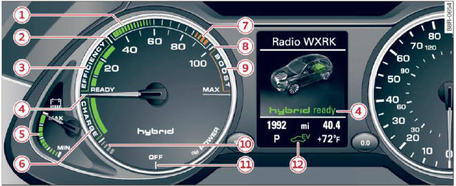
Fig. 110 Power meter overview

An economical driving and recuperation range is shown in green. A driving range that is not economical is shown in orange. In addition, the battery status provides information about the high voltage battery charge status.

  1. Fuel efficient driving within the combustion engine's partial load range
  2. System limits for electric driving in the EV mode
  3. Electric driving or driving with the combustion engine (EFFICIENCY)
  4. Vehicle drive ready (READY)
  5. High voltage battery charge status
  6. Recuperation (CHARGE)
  7. Driving within the combustion engine's full Load range
  8. 100% combustion engine
  9. Boosting - the electric engine assists the combustion engine (BOOST)
  10. Engaging the conventional brakes with recuperation
  11. Vehicle not drive ready (OFF)
  12. EV mode active

The needle remains at OFF when the ignition is turned on. When the vehicle enters drive ready mode, the status message appears briefly in the instrument cluster display and the needle in the power meter points to READY.

    READ NEXT:

     Indicator lights and messages

    Applies to vehicles: with hybrid drive The indicator lights in the instrument cluster blink or turn on. They indicate functions or malfunctions. With some indicator lights, messages may appear and a

     Hybrid functions and operating modes

    Applies to vehicles: with hybrid drive Fig. 111 Center console: button To turn on EV mode, press the button. The indicator light in the button will turn on. The indicator light also turns on

     Energy flow display

    Applies to vehicles: with hybrid drive Fig. 112 Instrument cluster: energy flow display The energy flow of the hybrid system is shown in the instrument cluster display and in the MMI display. The ima

    SEE MORE:

     Rear Window

    Overview - Rear Window 1 - Rear Window 2 - Adhesive Bead   Note Note varying spacing dimensions to window edge. Dimension -a- = 11 mm. Dimension -b- = 12.5 mm. Dimension -c- = 15.5 mm. 3 - Roof Spoiler Removing and Installing. Refer to → Chapter "O

     Service Station, Connecting with Connections on Low- and High Pressure Side of Refrigerant Circuit

    Servicing Station, Connecting for Measuring and Testing - Turn off the ignition. - Connect the service station to the power supply. - Connect the quick-release coupling adapter to the charging hoses of service station (handwheels not screwed in/hand shut-off valve not open). - 

    © 2019-2025 Copyright www.audiq5.net