Audi Q5: Drive Axle, Disassembling and Assembling
Special tools and workshop equipment required
- Press Plate -VW401-
- Press Plate -VW402-
- Press Piece - Rod -VW408A-
- Press Piece - Rod -VW411-
- Press Piece - 37mm -VW416B-
- Press Piece - Multiple Use -VW447H-
- Hose Clip Pliers -VAG1275A-
- Torque Wrench 1331 5-50Nm -VAG1331-
- Torque Wrench 1332 40-200Nm -VAG1332-
- Clamping Pliers -VAG1682A-
- Tripod Joint Tool -T10065-
- Slide Hammer Set -VW771-
- Triple Roller Assembly Tool -T40018- for triple roller joint AAR 3300 i, or
- Triple Roller Assembly Tool -T40084- for triple roller joint AAR 2600 i
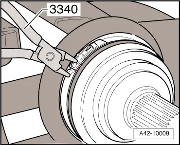
- Pliers -3340-
Triple Roller Joint AAR 2600 i or 3300 i, Disassembling
- Clamp the drive axle horizontally in the vise with protective covers.
 Note
Note
- Use vice clamp jaw protectors.
- Make sure that drive axle is not damaged.
- Mark the location of the joint to the drive axle
If they are not marked and are not installed in their previously installed positions, noises may occur later during driving operation.
- Mark the position of the joint protective boot to the joint.
A waterproof felt pen is well-suited for marking.
- Open clamps -arrows-.
- Slide back protective boot.
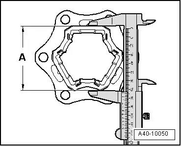
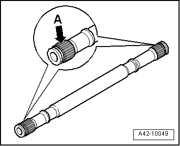
Distinguishing characteristic of drive axle AAR 2600 i to AAR 3300 i
- Determine dimension -A- as shown in illustration.
- Dimension -A- 74 mm = drive axle AAR 2600 i
- Dimension -A- 77 mm = drive axle AAR 3300 i
 Caution
Make sure that correct special tool allocation for each drive axle.
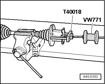
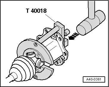
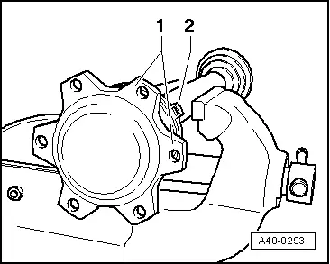
- Guide triple roller joint AAR 3300 i Triple Roller Assembly Tool -T40018- or triple roller joint AAR 2600 i Triple Roller Assembly Tool -T40084- behind joint.
Guide pins -1- must contact joint.
- Move the Triple Roller Assembly Tool -T40018- up against the joint by turning knurled screws -2-.
 Note
Note
- Joint must be secured without play in Triple Roller Assembly Tool -T40018- or Triple Roller Assembly Tool -T40084-.
- Tighten the screws -2- by hand only.
- Install the Slide Hammer Set -VW771- in the Triple Roller Assembly Tool -T40018- or the Triple Roller Assembly Tool -T40084-.
Drive Axle AAR 3300 i Triple Roller Assembly Tool -T40018- is shown in illustration.
Use Triple Roller Assembly Tool -T40084- with drive axle AAR 2600 i.
- Remove the joint horizontally using the Slide Hammer Set -VW771-.
- Leave the joint in the Triple Roller Assembly Tool -T40018- or the Triple Roller Assembly Tool -T40084-.
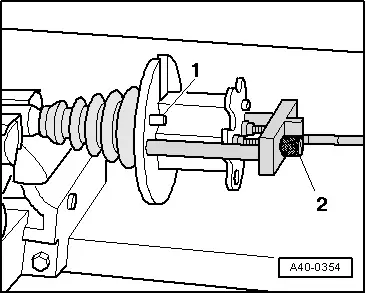
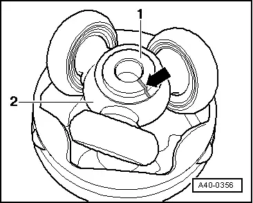
- Mark installation position of the parts -1- and -2- with lines.
If they are not marked and are not installed in their previously installed positions, noises may occur later during driving operation.
A waterproof felt pen is well-suited for marking.
1 - Drive Axle
2 - Triple roller star
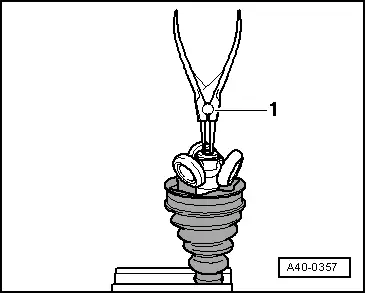
- Remove grease with lint-free cloth.
- Remove the circlip.
1 - Pliers (commercially available)
Press triple roller star off of drive axle
- Use special tool shown in illustration.
1 - Assembly Tool -T10065/1-
2 - Triple Roller Assembly Tool -T10065/5- - must touch the triple roller star base
3 - Press Plate -VW401-
4 - Press Piece - Rod -VW408A-
5 - Press Plate -VW402-
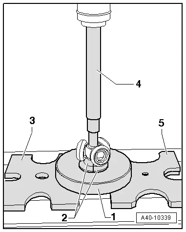
The Triple Roller Assembly Tool -T10065/5- must not touch the rollers; move the rollers to the side if necessary.
- Remove the protective boot.
- Remove the grease on the shaft splines.
- Check the roller body and ball cage for wear.
- Clean drive axle and housing.
Triple Roller Joint AAR 2600 i or 3300 i, Assembling
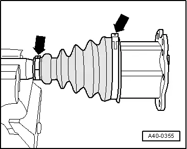
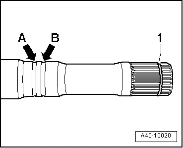
- Slide on the small clamp with the protective boot and position the protective boot on the drive axle according to the version.
Version with identification groove:
- Position CV boot in outer groove -arrow B-.
Inner groove -arrow A- must remain visible "identification groove" (for correct installation of joint protective boot).
Version with base:
- Position protective joint boot between -arrows-.

Tripod roller star, pressing onto drive axle
The chamfer on the triple roller star faces the drive axle. This is used as an assembly aid.
- Before installing joint or triple roller star, splines -A- must be lightly coated with grease used in joint.
- Place the triple roller star on the shaft according to the marking and drive on to the stop.
Use the Triple Roller Assembly Tool -T10065/6- and make sure it attaches to the bead at the bottom -arrow- in the drive axle.
- Use special tool shown in illustration.
1 - Assembly Tool -T10065/1-
2 - Triple Roller Assembly Tool -T10065/6- - must attach to the bead at the bottom of the drive axle -arrow-.
3 - Press Plate -VW401-
4 - Press Piece - 37mm -VW416B-
5 - Press Piece - Multiple Use -VW447H-
6 - Press Piece - Rod -VW411-
7 - Press Plate -VW402-
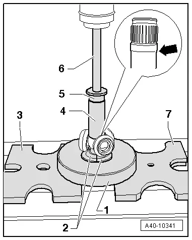
The Triple Roller Assembly Tool -T10065/6- must not touch the roller; move the rollers to the side if necessary.
- Press the triple roller joint onto the drive axle.
- Install circlip.
- Circlip must engage audibly, triple roller star must lie against circlip with no gap.
1 - Pliers (commercially available)
- Press 70 grams of joint grease, from repair set, into the reverse side of the triple roller joint.
- Lightly grease the roller body.
Make sure roller body does not tilt!

- Press the joint over the triple roller star using a plastic hammer.
Drive Axle AAR 3300 i Triple Roller Assembly Tool -T40018- is shown in illustration.
- Press remaining quantity of grease in protective boot.
- Slide the protective boot onto the joint.
- Make sure the joint protective boot fits correctly on the joint; align the boot if necessary.
- Protective joint boot must fit in groove and on joint contour.
 Note
Note
It is necessary to let the air out of the joint protective boot when positioning it on the joint. Use a screwdriver to let the air out.
- Install clamp.
 Note
Note
For a better alignment of multipoint socket head screws when installing drive axle, clamping sleeve connecting tube -2- must be between joint connecting flanges -1-.
- Install the clamps on the triple roller joint. Refer to → Chapter "Clamp on Triple Roller Joint and Outer Joint, Tensioning".
CV Joint, Servicing
Special tools and workshop equipment required
- Copper or Brass Drift
Outer CV joint, removing
- Secure the drive axle in the vise with protective covers.
- Open both clamping sleeves and remove protective joint boot from outer joint.
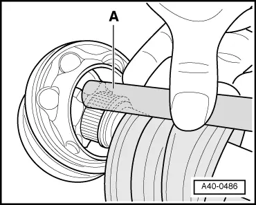
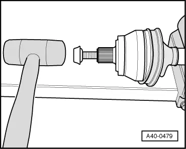
- Strike a copper or brass drift -A- on CV joint inner race with a hammer.
- Remove joint and protective joint boot.
Outer CV Joint, Installing
There must be no grease on the boot or on the drive axle where the boot contacts them.
- Always replace the circlip -1-.
- Slide on the small clamp with the protective boot and position the protective boot on the drive axle according to the version.

Version with identification groove:
- Position CV boot in outer groove -arrow B-.
Inner groove -arrow A- must remain visible "identification groove" (for correct installation of joint protective boot).

Version with base:
- Position protective joint boot between -arrows-.
- Add the specified quantity of grease to the inner joint. See the table.
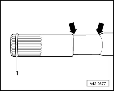
- Before installing the joint, splines -A- must be lightly coated with the grease used in the joint.
- Insert sealing ring in groove on shaft.

- Slide on CV joint up to sealing ring.
- Align sealing ring at center with opening upward -see arrows-.
- Screw old drive axle screw into joint as shown in the illustration.
- Drive joint onto drive axle with plastic hammer until circlip engages.
- Add the specified quantity of grease to the inner joint. See the table.
- Slide the protective boot onto the joint.
- Bleed protective joint boot.
- Make sure the protective boot is seated on the joint correctly.
- Protective joint boot must fit in groove and on joint contour.
- Tension the clamps on outer joint. Refer to → Chapter "Clamp on Triple Roller Joint and Outer Joint, Tensioning".
Outer CV Joint, Checking
It is necessary to disassemble the joint whenever replacing the grease or if the ball surfaces show wear or damage.
Disassembling
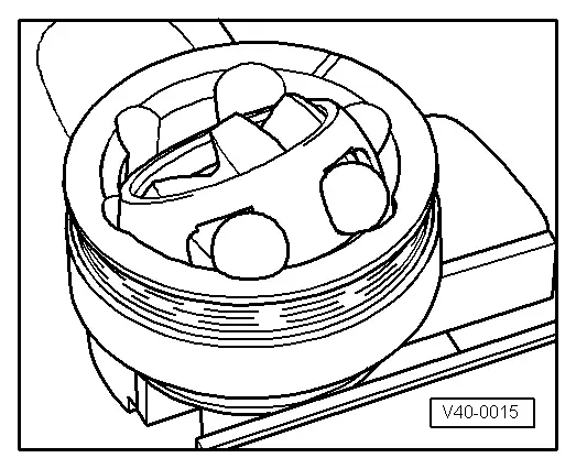
- Mark position of ball hub to ball cage and to housing before disassembling, using electro-writer or grindstone.
- Swivel the ball hub and ball bearing cage.
- Remove the balls one after the other.
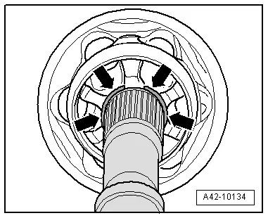
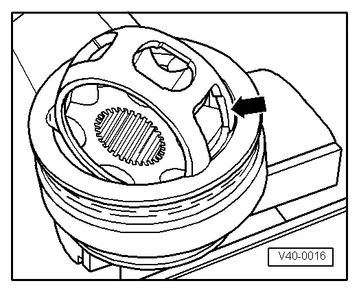
- Turn cage, until two rectangular windows -arrow- contact joint body.
- Lift out cage with hub.
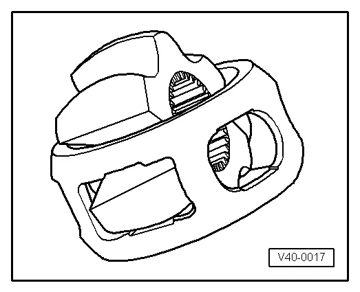
- Swing hub segment with smaller pins into rectangular window on cage.
- Fold hub out from cage.
Checking
6 balls for each joint belong to a tolerance group. Check stub axle, hub, cage and balls for small depressions (pitting build-up) and chafing. Excessive circumferential backlash in joint makes itself noticed via tip-in shock, in such cases joint should be replaced. Flattening and running marks of balls are no reason to replace joint.
Assembling
- Insert cage with hub into joint body.
 Note
Note
Cage must be installed laterally correct.
- Press in opposing balls in sequence, during this, previous position of ball hub to ball cage and to joint body must be established again.
- Press the grease into the joint body.
Clamp on Triple Roller Joint and Outer Joint, Tensioning
Depending on the version of the clamp, use the following tools:
Special tools and workshop equipment required
- Pliers -3340-
- Clamping Pliers -VAG1682A-
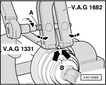
Mount and tension stainless steel clamps using Clamping Pliers -VAG1682A- as illustrated.
- When doing this, make sure that edges of clamping pliers are seated in corners -arrows B- of clamp.
- Tighten the clamp by turning the spindle using a torque wrench -C- (do not tilt the pliers).
- The hard material of the CV boot (compared to rubber) makes it necessary to use a stainless steel hose clamp. It is only possible to tighten the hose clamp with Clamping Pliers -VAG1682A-.
- Tightening specification: 20 Nm.
- Use torque wrench with 5 to 50 Nm range (for example, Torque Wrench 1331 5-50Nm -VAG1331-).
- Make sure the thread on the spindle -A- is easy to move. Lubricate with MoS2 grease if necessary.
- If the thread is tight, for example, dirty, the required tensioning force for the hose clamp will not be achieved in spite of correct torque specification settings.
Mount and tension the clamp with the retaining tabs using Pliers -3340- as illustrated.
- Engage the clamp at the first catch by hand.
- Close the clamp using Pliers -3340-.