Audi Q5: Door Handle Trim Molding, Removing and Installing
Door Handle Trim Molding, Removing and Installing
Removing
- Remove the door handle. Refer to → Chapter "Door Handle, Removing and Installing".
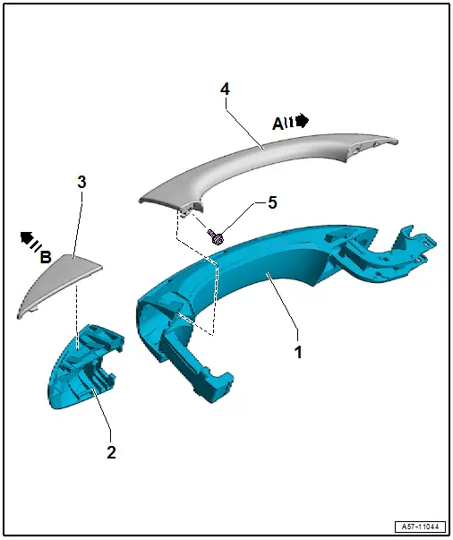
- Remove the bolt -5-.
- Remove the trim molding -4- from the door handle -1--arrow A-.
Installing
Install in reverse order of removal and note the following:
- Tighten the screw -5- 0.2 Nm.
- The bolt head must not project over the contact surface for the tread.
Cap Trim Molding, Removing and Installing
Removing
- Remove the cap. Refer to → Chapter "Lock Cylinder Cap, Removing and Installing".
- Remove the trim molding -3- from the cap -2--arrow B-.
Installing
Install in reverse order of removal.
Left and Right Front Outside Door Handle Touch Sensors -G605-/-G606-, Removing and Installing
 Caution
To prevent damaging the sensor, follow the instructions only as described.
- Remove the exterior door handle -2- and sensor -1-. Refer to → Chapter "Door Handle, Removing and Installing".
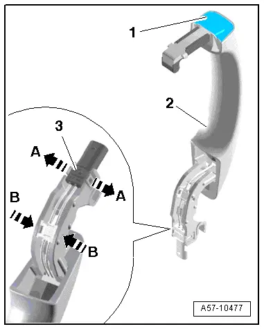
- Using a small screwdriver, carefully release the latches at the arrows - A and B- and push the connector -3- and the wiring guide to the side.
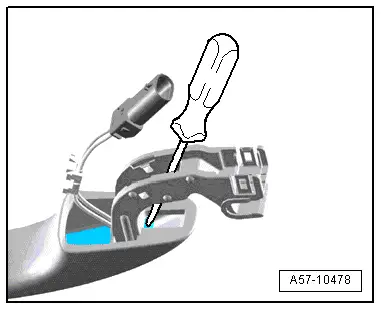
- Insert a screwdriver into the exterior door handle so that it is front of the sensor as illustrated.
- With light force on the screwdriver, pry out the sensor from the exterior door handle.
- Remove the sensor from the exterior door handle.