Audi Q5: Connector Assignments
Navigation Connector Assignment
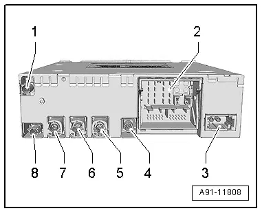
Information Electronics Control Module 1 -J794-
1 - Not Assigned
2 - Connection block with four multipin connectors
3 - MOST Bus
4 - CVBS input
5 - 4-pin connector (T4al/T4am) for the Front Information Display Control Head -J685-
6 - 4-pin connector (T4ap) to External Audio Source Connection -R199-
7 - Not Assigned
8 - Antenna Connection (GPS) from the Roof Antenna -R216-
 Note
Note
Unlisted connector terminals are not assigned.
2 - Connection block with four multipin connectors
A - Brown 8-pin connector (T8ah)
1 - LF mute wire from preliminary setup for cell phone preparation
2 - Power Supply to Multimedia System Control Head -E380-
3 - Wake UP to Multimedia System Control Head -E380-
4 - Not Assigned
5 - Not Assigned
6 - Reset to the Multimedia System Control Head -E380-
7 - Ring-break Diagnostic Cable

B - Blue 12-pin connector (T12x)
2 - Microphone IN (+) for the Microphone Unit in Front Roof Module -R164- (Right Front Microphone -R141-)
3 - Microphone IN (-) for the Microphone Unit in Front Roof Module -R164- (Right Front Microphone -R141-)
5 - CVBS cable (-) for the Rearview Camera System Control Module -J772-
11 - CVBS cable (+) for the Rearview Camera System Control Module -J772-

C - Green 12-pin connector (T12y)
All pins are connected to the External Audio Source Connection -R199-.
1 - LF-In ground
2 - Right LF-In
3 - USB (+5V)
4 - USB (ground)
5 - Not Assigned
6 - Detect
7 - Left LF-In
8 - LF-In ground shielding
9 - CVBS cable (+)
10 - CVBS cable (-)
11 - iPod data
12 - iPod data
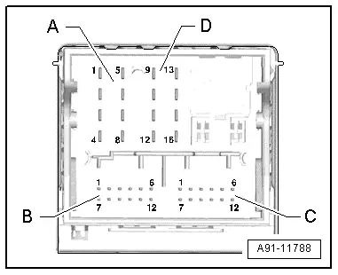
D - Black 8-pin connector (T16q)
10 - Data from Multimedia System Control Head -E380-
11 - Data to the Multimedia System Control Head -E380-
12 - Terminal 31
14 - Reset from Multimedia System Control Head -E380-
15 - Terminal 30
16 - Ground to Multimedia System Control Head -E380-

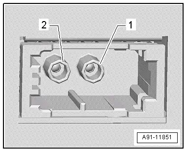
3 - MOST Bus
1 - Input
2 - Output
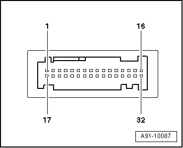
Chip Card Reader Control Module -J676-, Connector Assignment
Chip Card Reader Control Module -J676-
 Note
Note
Unlisted connector terminals are not assigned.
Multipin connector, 32-pin black
1-16 - to the Traffic Data Antenna -R173-
17 - VICS data wire to the Information Electronics Control Module 1 -J794-
19 - VICS data wire to the Information Electronics Control Module 1 -J794-
21 - Switch-on signal to the Information Electronics Control Module 1 -J794-
22 - Terminal 30
23 - ETC data to the Information Electronics Control Module 1 -J794-
25 - ETC data from the Information Electronics Control Module 1 -J794-
28 - Terminal 31
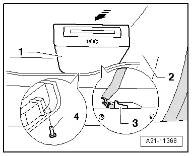
Chip Card Reader Control Module, Removing and Installing
The Chip Chard Reader Control Module -J676- slides onto the glove compartment trim.
- Turn off the ignition and all electrical consumers and remove the ignition key.
 WARNING
Danger of unintended engine ignition
Turn off the ignition and remove the ignition key from the vehicle interior for all work performed on the high voltage vehicle.
Removing
- Open the glove compartment.
- Remove the chip card.
- Slide the Chip Card Reader Control Module -J676--1- toward the rear, in the direction of -arrow-, until it can be removed from the trim -2-.
- Remove retaining clip -4-.
- Disconnect the connector -3- from the Chip Card Reader Control Module -J676--1-.
Installing
- Install in reverse order of removal.
- Make sure that all tabs on the Chip Card Reader Control Module -J676- engage in trim.
Tightening specifications and installation instructions can be found in the Component Location Overview. Refer to → Chapter "Navigation System Component Location Overview, Japan".