Audi Q5: Connection for External Multimedia Devices
Overview - Connection for External Multimedia Devices
There are several External Audio Source Connection -R199- versions:
CAN versions
The AMI (Audi Music Interface) version is installed in the glove compartment.
The AUX IN socket version is installed in the center console storage compartment.
These External Audio Source Connection -R199- are connected directly to the Radio -R-.
Either an AMI or AUX IN socket is installed.
MMI versions
The AMI (Audi Music Interface) is a component of the Information Electronics Control Module 1 -J794-.
The interface is located in the glove compartment.
The AUX IN socket version is installed in the center console storage compartment.
These External Audio Source Connections -R199- are connected directly to the Information Electronics Control Module 1 -J794-.
Either an AMI or AUX IN socket is installed.
Different external audio sources can be connected to the External Audio Source Connection -R199-:
- iPod
- MP3 player
- USB Stick
Suitable adapter cables are needed. Refer to the Owner's Manual.
Perform the Fault Finding with the Vehicle Diagnostic Tester.
External Audio Source Connection Connectors
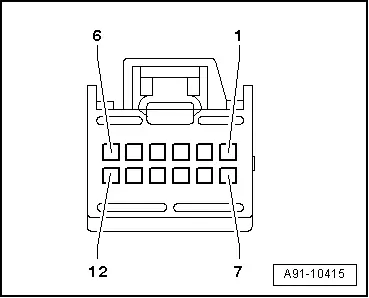
External Audio Source Connection -R199- Connector Assignment, AMI, CAN
 Note
Note
Unlisted connector terminals are not assigned.
12-pin connector (T12t)
1 - Terminal 31
2 - CAN Bus low (Infotainment)
3 - Not Assigned
4 - LF right to the Radio -R-
5 - Not Assigned
6 - Not Assigned
7 - Terminal 30
8 - CAN Bus high (Infotainment)
9 - LF left to the Radio -R-
10 - LF ground to the Radio -R-
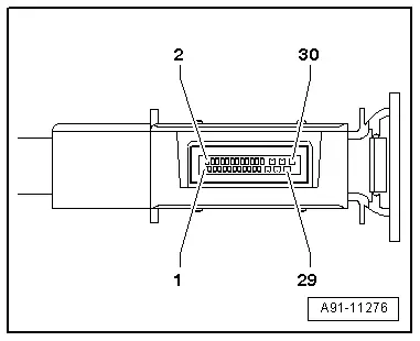
External Audio Source Connection -R199- Connector Assignment, Interface MMI
 Note
Note
Unlisted connector terminals are not assigned.
Black 30-pin connector (T30b)
All pins are connected to the Information Electronics Control Module 1 -J794-.
1 - Left LF-In
2 - Right LF-In
3 - LF ground
4 - LF-In ground shielding
13 - iPod data
14 - iPod data
16 - iPod recognized
17 - D (+)
18 - D (-)
21 - Detect
22 - Ground
24 - CVBS cable (-)
25 - USB (ground)
27 - CVBS cable (+)
28 - USB (+5V)
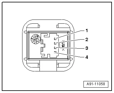
External Audio Source Connection -R199-, Connector Assignment, AUX IN
 Note
Note
Unlisted connector terminals are not assigned.
4-pin multipin connector (T4i) (CAN)
All pins are connected to the Radio -R-.
1 - LF ground
2 - LF left
3 - LF right
4 - Terminal 31
5-pin multipin connector (T5g) (MMI)
All pins are connected to the Information Electronics Control Module 1 -J794-.
1 - LF ground
2 - LF left
3 - LF right
4 - Ground Shielding
5 - Detect
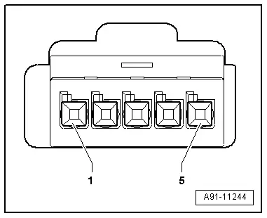
External Audio Source Connection -R199-, Removing and Installing
External Audio Source Connection -R199-, Removing and Installing, AMI
Special tools and workshop equipment required
- Radio Removal Tool -T10057-
- Fiber Optic Repair Set -VAS6223B-
- Fiber-Optic Repair Set - Connector Protective Caps -VAS6223/9-.
The External Audio Source Connection -R199- (AMI) is located inside the glove compartment.
- Turn off the ignition and all electrical consumers and remove the ignition key.
 WARNING
Danger of unintended engine ignition
Turn off the ignition and remove the ignition key from the vehicle interior for all work performed on the high voltage vehicle.
Removing
- Open the glove compartment.
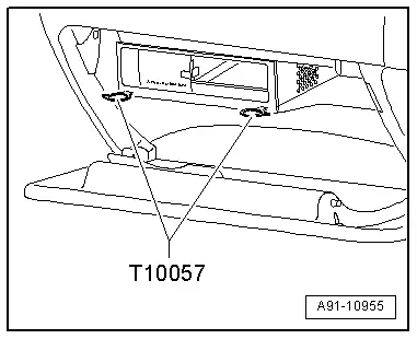
- Insert the two clips of the Radio Removal Tool -T10057- into the slits on the External Audio Source Connection -R199- until they engage. Points on the grip eyelets of tool face outward.
- Pull External Audio Source Connection -R199- out of mounting frame.
- Disconnect all connectors on the External Audio Source Connection -R199-.
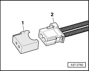
Versions with MOST Bus
- Insert the Fiber-Optic Repair Set - Connector Protective Caps -VAS6223/9--1- onto the MOST Bus connector -2-.
All
- Remove the Radio Removal Tool -T10057-, push locking tabs on External Audio Source Connection -R199- to do so.
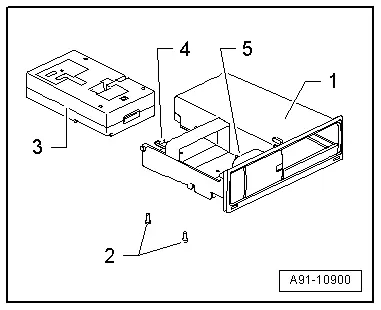
Remove the internal control unit
- Remove the screw -2- on back side (2 Nm).
- Press the tabs -4- and -5- down and up and remove the control module -3- backwards from the frame -1-.
Installing
- Connect all connectors.
- Slide the External Audio Source Connection -R199- on the mounting frame until it engages.
Tightening specifications and installation instructions can be found in the Component Location Overview. Refer to → Chapter "Component Location Overview - Infotainment System".
External Audio Source Connection -R199-, Removing and Installing, AUX IN
The External Audio Source Connection -R199- (AUX IN) is located in the center console storage compartment.
- Turn off the ignition and all electrical consumers and remove the ignition key.
 WARNING
Danger of unintended engine ignition
Turn off the ignition and remove the ignition key from the vehicle interior for all work performed on the high voltage vehicle.
Removing
- Remove the center console storage compartment. Refer to → Body Interior; Rep. Gr.68; Center Console; Front Center Console Storage Compartment, Removing and Installing.
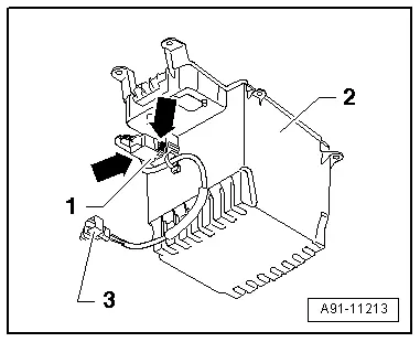
- Disconnect the connector -3- on the External Audio Source Connection -R199--1-.
- Squeeze together the retaining tabs -arrow- on the External Audio Source Connection -R199--1- and slide the External Audio Source Connection -R199--1- out of the storage compartment -2-.
Installing
- Install in reverse order of removal.
Tightening specifications and installation instructions can be found in the Component Location Overview. Refer to → Chapter "Component Location Overview - Radio".
External Audio Source Connection -R199-, Removing and Installing, Interface
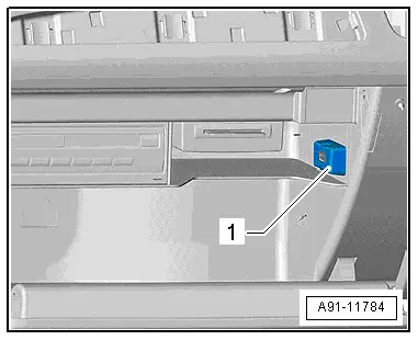
The External Audio Source Connection -R199- (interface) -1- is located inside the glove compartment.
- Turn off the ignition and all electrical consumers and remove the ignition key.
 WARNING
Danger of unintended engine ignition
Turn off the ignition and remove the ignition key from the vehicle interior for all work performed on the high voltage vehicle.
Removing
The wires for the interface are components of the wiring harness. They cannot be replaced separately. If faulty, the adapter cable must be installed. Refer to the Parts Catalog.
- Open the glove compartment.
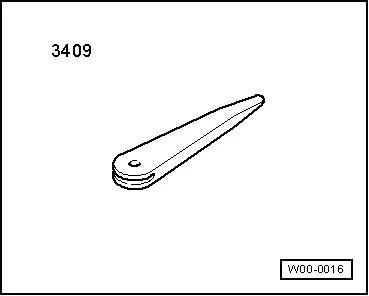
- Unclip the trim -1- using the Trim Removal Wedge -3409-.
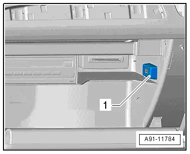
The interface (T30b) -1- is installed from behind in the glove compartment.
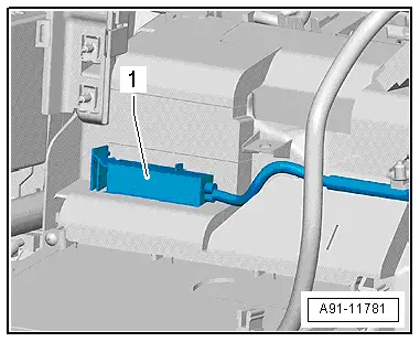
The connectors for the interface T4ap -1- and T12y -2- are found on the Information Electronics Control Module 1 -J794-.
Installing
- Install in reverse order of removal.
Tightening specifications and installation instructions can be found in the Component Location Overview. Refer to → Chapter "Component Location Overview - Infotainment System".
Special Tools
Special tools and workshop equipment required
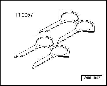
- Radio Removal Tool -T10057-
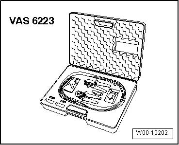
- Fiber Optic Repair Set -VAS6223B-
- Fiber-Optic Repair Set - Connector Protective Caps -VAS6223/9-.
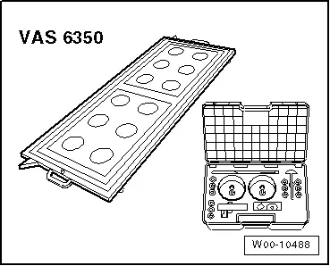
- Calibration Tool -VAS6350-
- Trim Removal Wedge -3409-
Edition: A005Q502521 - LC - 05/07/2015 - TMP
