Audi Q5: Checking Pressures for Vehicles with Restrictor and Reservoir (with Internally Regulated Compressor)
General Information
 Note
Note
- Connect the A/C service station. Refer to → Chapter "A/C Service Station, Connecting".
- Observe the test requirements. Refer to → Chapter "Pressures, Checking".
- With the ignition switched off, check the pressure in the refrigerant circuit (using the service station). Refer to → Chapter "Refrigerant Circuit, Checking Pressure with Service Station".
The pressures with the ignition turned off meet the specifications.
- Start the engine.
- Bring the engine speed up to 2000 RPM.
- Observe the pressure gauge of the service station.
 Note
Note
- The switch pressures for refrigerant circuit switches are vehicle-specific.
- The connection with valve for low-pressure switch or at evaporator is only to be used for vehicles with no service connection on low-pressure side and inaccessible connection at compressor or accumulator (measurement accuracy). Only applies to specific vehicles. Refer to → Heating, Ventilation and Air Conditioning; Rep. Gr.87; System Overview - Refrigerant Circuit (vehicle-specific repair manual).
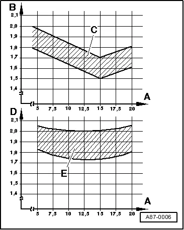
Specified Values for the Refrigerant Circuit Pressures
High-Pressure Side:
Increasing from initial pressure (when connecting the pressure gauges) to a maximum of 20 bar (290 psi).
Low-Pressure Side:
Decreasing from initial pressure (when connecting pressure gauges) to the value in the graph.
A - High pressure (measured at service connection) in bar (psi)
B - Low pressure (measured at connection with valve at compressor or accumulator) in bar
C - Permissible tolerance range
D - Low pressure (measured at connection with valve for low-pressure switch or at service connection) in bar (psi)
E - Permissible tolerance range
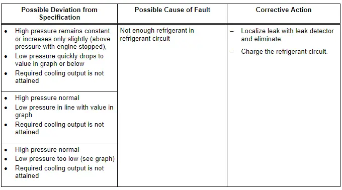
 Note
Note
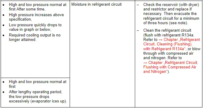
If no fault is found with this malfunction, clean the refrigerant circuit (flush using refrigerant R134a. Refer to → Chapter "Refrigerant Circuit, Cleaning (Flushing), with Refrigerant R134a"; or blow through using compressed air and nitrogen. Refer to → Chapter "Refrigerant Circuit, Flushing with Compressed Air and Nitrogen").
 Note
Note
- If problem involving moisture in refrigerant circuit only occurs after a lengthy operating period or only infrequently (low pressure drops below specification and evaporator ices up), it is sufficient to replace the dryer (adjust quantity of refrigerant oil). Refrigerant circuit is then to be evacuated for at least three hours.
- It is not initially necessary to clean the refrigerant circuit (flush using refrigerant R134a. Refer to → Chapter "Refrigerant Circuit, Cleaning (Flushing), with Refrigerant R134a". Or blow through using compressed air and nitrogen. Refer to → Chapter "Refrigerant Circuit, Flushing with Compressed Air and Nitrogen" when this problem occurs since normally there is only a small quantity of moisture in the system which can be removed by lengthy evacuation.
 Note
Note
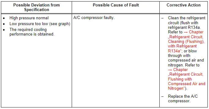
- For the malfunction "high pressure normal, low pressure too low", note the following: This fault may cause the evaporator to ice up or the A/C Refrigerant Low Pressure Switch -F73- to shut off the compressor although the amount of refrigerant in the circuit is OK.
- On the Audi 100, Audi A6 (through MY1997) and Audi V8, this fault may result in compressor being shut off by the control head (if the temperature at fresh-air blower drops below -3 ºC (27 ºF) ). Refer to → Heating, Ventilation and Air Conditioning; Rep. Gr.87; System Overview - Refrigerant Circuit or →Heating, Ventilation and Air Conditioning; Rep. Gr.87 (vehicle-specific repair manual).
 Note
Note
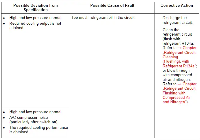
- Overfilling with refrigerant oil can occur if, for example, the compressor has been replaced without adjusting the quantity of refrigerant oil.
- If there is too much refrigerant oil in the circuit, the compressor must be drained and the accumulator must be replaced. After cleaning the refrigerant circuit (flushing with refrigerant R134a. Refer to → Chapter "Refrigerant Circuit, Cleaning (Flushing), with Refrigerant R134a"; or blowing through using compressed air and nitrogen. Refer to → Chapter "Refrigerant Circuit, Flushing with Compressed Air and Nitrogen"), the correct quantity of refrigerant oil is filled into the circuit. Refer to → Chapter "Approved Refrigerant Oils and Capacities".

