Audi Q5: Battery Charger -VAS5900- Support Mode
General Information
The support mode provides the vehicle electrical system with voltage when the Battery -A- is removed or disconnected.
For more information. Refer to the Battery Charger -VAS5900- Operating Instructions.
The support mode is used for the following situations:
- Vehicle electrical system support mode with the Battery -A- not installed
- Maintaining the voltage when the battery is being replaced
- Systems test without the Battery -A-
 WARNING
Risk of injury. Follow all warning messages and safety precautions. Refer to → Chapter "Warnings and Safety Precautions".
 WARNING
Do not check or charge a Battery -A- when the visual indicator has "no color or is bright yellow". Jump starting must not be used!
There is a risk of explosion during testing, charging or jump starting.
These Batteries -A- must be replaced.
Special tools and workshop equipment required
- Battery Charger -VAS5900-
Procedure
 Caution
- The polarity protection of the charger clamps is not active in the operation mode "charging severely discharged batteries/Support mode". Connect the charger clamps to the battery terminals correctly according to polarity!
- It can result in sparks due to short circuit.
- This constitutes an explosion risk.
- Do not touch START / STOP button when battery cables are incorrectly connected! The Battery Charger -VAS5900- can become damaged.
- Remove the Battery -A-. Refer to → Electrical Equipment; Rep. Gr.27; Battery; Battery, Removing and Installing.
- Connect the Battery Charger -VAS5900- to the power supply. The last selected mode is shown on the display. Refer to → Chapter "Battery Charger -VAS5900- Device Description".
 Caution
Whenever the Battery -A- is removed, be careful to prevent contact between the connected charge clamp on the positive terminal and the body ground. Likewise prevent contact between the battery terminals.
- Connect the red charge terminal (+) to the positive terminal of the Battery -A-.
 Note
Note
On vehicles with a Start/Stop function and an installed Battery Monitoring Control Module -J367-, the black charge terminal (-) must be connected to the body ground. The Start/Stop system will malfunction when it is connected to the Battery -A- negative terminal.
- Connect the black charge terminal (-) to the negative terminal of the Battery -A-/negative connector.
- Press the START/STOP button for about 5 seconds. The menu selection "Charging severely discharged batteries/Support mode" is activated.
- Press the corresponding ↑-button or ↓ button to adjust the battery voltage(6 V/12 V/24 V).
 Note
Note
If no button is touched within five seconds, the Battery Charger -VAS5900- will return to the main menu (operating mode selection).
- Select the battery voltage by pressing the START/STOP button.
Then the inquiry about the correct polarity of the charging clamps is made.
- Check correct polarity connection of charger clamps.
- Confirm charging clamps are connected to correct poles via START/STOP button.
The Battery Charger -VAS5900- starts the Battery -A- support mode.
End the Battery Support Mode
- Press the START/STOP-button.
- Remove the charging clamps from the battery terminals.
- Disconnect the Battery Charger -VAS5900- from the power.
Battery Charger -VAS5900- Maintenance Charging
 Note
Note
- If the Battery -A- is discharged by an electrical consumer during maintenance charging, the Battery Charger -VAS5900- automatically supplies the appropriate charge.
- Maintenance charging can be performed without time restrictions.
- The Battery -A- can be used constantly.
- Observe the maintenance notes of the battery manufacturer.
 WARNING
Risk of injury. Follow all warning messages and safety precautions. Refer to → Chapter "Warnings and Safety Precautions".
 WARNING
Do not check or charge a Battery -A- when the visual indicator has "no color or is bright yellow". Jump starting must not be used!
There is a risk of explosion during testing, charging or jump starting.
These Batteries -A- must be replaced.
If the Battery -A- is fully charged, the Battery Charger -VAS5900- starts maintenance charging.
Special tools and workshop equipment required
- Battery Charger -VAS5900-
Procedure
- Proceed as if charging the Battery -A-. Refer to → Chapter "Battery, Charging with Battery Charger -VAS5900-".
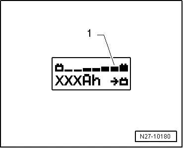
With a charge status of 100%, all bars are indicated on the display -1-.


