Audi Q5: Switching the Start-Stop-System on/off manually
Applies to vehicles: with Start-Stop-System
If you do not wish to use the system, you can switch it off manually.

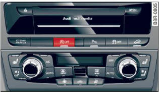
Fig. 106 Center console: Start -Stop-System button
- To switch the Start-Stop-System on/off manually,
press the
.png) button. The LED in
the button
turns on when the system is switched off.
button. The LED in
the button
turns on when the system is switched off.
In vehicles without the MMI, the .png) button is
found underneath the selector lever.
button is
found underneath the selector lever.
Tips
If you switch the system off during a stop phase, the engine will start again automatically.
Messages in the instrument cluster display
Applies to vehicles: with Start-Stop-System
Start-stop system: deactivated. Please restart engine manually
This message appears when specific conditions are not met during a stop phase and the Start-Stop-System will not be able to restart the engine.
The engine must be started with the key or with the [START ENGINE STOP] button.
Start-stop system: system fault. Function unavailable
There is a malfunction in the Start-Stop-System.
Drive the vehicle to an authorized repair facility for servicing as soon as possible to correct the malfunction.
Transmission: Car may roll! Shift to park!
This message appears if the selector lever is not in the P position when the driver's door is opened. You will also hear a warning tone. Shift the selector lever to the P position. Otherwise, the vehicle could roll.

