Audi Q5: Subwoofer -R211-, Removing and Installing
Subwoofer In Rear Shelf -R157-, Removing and Installing
The Subwoofer in Rear Shelf - R157- is located in the spare tire well.
- Turn off the ignition and all electrical consumers and remove the ignition key.
Removing
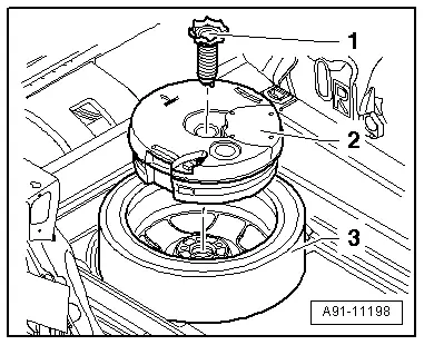
- Remove the screw -1- from the Subwoofer in Rear Shelf -R157--2-.
- Disconnect the connector from the Subwoofer in Rear Shelf -R157--2- and remove the Subwoofer in Rear Shelf -R157--2- upward and out of the spare tire well -3-.
Installing
- Install in reverse order of removal.
Tightening specifications and installation instructions can be found in the Component Location Overview. Refer to → Chapter "Component Location Overview - Sound System, Basic/Standard".
Subwoofer in Rear Shelf -R157-, Removing and Installing, High Voltage Vehicle
The Subwoofer in Rear Shelf - R157- is located in the spare tire well.
It is not required to activate the vehicle.
- Turn off the ignition and all electrical consumers and remove the ignition key.
 WARNING
Danger of unintended engine ignition
Turn off the ignition and remove the ignition key from the vehicle interior for all work performed on the high voltage vehicle.
 DANGER!
Damaged high voltage components may produce dangerously high voltage.
Note the following when working near high voltage components and cables:
- Do not use tools that have sharp edges, that are used for cutting or shaping, or that generate heat, such as welding, soldering, hot air or thermal adhesive equipment.
- Inspect the high voltage components in the area where the work will be performed before starting the procedure.
- Perform a visual inspection of the Electric Drive Power and Control Electronics -JX1-, the Electro-Drive Drive Motor -V141-, the Electrical A/C Compressor -V470- and the high voltage cables when working inside the engine compartment.
- Perform a visual inspection of the high voltage cables and the covers when working on the floor panel.
- Perform a visual inspection of the high voltage cables and the electro-box with the High Voltage System Maintenance Connector -TW- when working in the rear of the vehicle.
- Perform a visual inspection of all of the potential equalization cables.
Note the following when performing the visual inspection:
- None of the components may display any exterior damage.
- The high voltage cable insulation and the potential equalization cables may not be damaged.
- The high voltage cables may not be deformed in any way.
- Each high voltage component muss be labeled with a red warning label.
Removing
- Remove the rear luggage compartment floor. Refer to → Body Interior; Rep. Gr.70; Luggage Compartment Trim Panels; Luggage Compartment Floor Panel, Removing and Installing.
- Set the battery cooling module for the Traction Battery -A2- in the service position. Refer to →Heating, Ventilation and Air Conditioning; Rep. Gr.87.
- Remove the rear lid end trim panel. Refer to → Body Interior; Rep. Gr.70; Luggage Compartment Trim Panels; Lock Carrier Trim Panel, Removing and Installing.
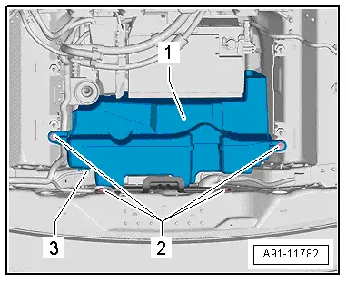
- Disconnect the connector -3- from the Subwoofer in Rear Shelf -R157--1-.
- Remove the bolts -2- from the Subwoofer in Rear Shelf - R157--1-.
- Remove the Subwoofer in Rear Shelf -R157--1- with bracket from the spare tire well.
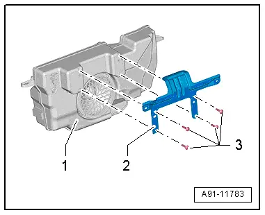
- Remove the bolts -3- from the bracket -2- and remove the bracket -2- from the Subwoofer in Rear Shelf -R157--1-.
Installing
- Install in reverse order of removal.
Tightening specifications and installation instructions can be found in the Component Location Overview. Refer to → Chapter "Component Location Overview - Sound System, Basic/Standard".
Center Speaker, Removing and Installing
Center Mid-Treble Speaker -R158-
The Center Mid-Treble Speaker -R158- is located in the front center of the instrument panel.
- Turn off the ignition and all electrical consumers and remove the ignition key.
 WARNING
Danger of unintended engine ignition
Turn off the ignition and remove the ignition key from the vehicle interior for all work performed on the high voltage vehicle.
Removing
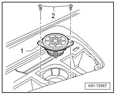
- Unclip the speaker trim from the instrument panel.
- Remove the screws -2- from the Center Mid-Treble Speaker -R158--1-.
- Disconnect the connector on the Center Mid-Treble Speaker -R158--1- and remove the Center Mid-Treble Speaker -R158--1- from the instrument panel.
Installing
- Install in reverse order of removal.
Tightening specifications and installation instructions can be found in the Component Location Overview. Refer to → Chapter "Component Location Overview - Sound System, Basic/Standard".