Final Drive 0BC Removing and Installing, Audi Q5 Hybrid
Special tools and workshop equipment required
- Engine and Gearbox Jack -VAS6931- with Universal Transmission Support -VAG359/2-
- Tensioning Strap -T10038-
- Engine/Gearbox Jack Adapter - Wheel Hub Support - T10149-
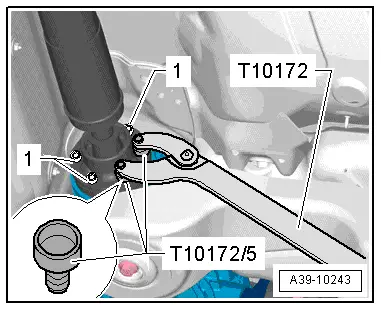
- Counterhold - Kit - Multiple Use -T10172- with Counterhold - Kit - Adapter 5 - T10172/5-
- Socket - Xzn 12 -T40154-
Removal
Pay attention to the safety precautions. Refer to → Chapter "Safety Precautions".
Pay attention to the general repair information. Refer to → Chapter "Repair Information".
- Place the vehicle on a lift.
De-energizing the High-Voltage System
 WARNING
Follow the High-Voltage System General Warnings. Refer to → Electrical System Hybrid; Rep. Gr.93; High Voltage System General Warnings.
Turning off the voltage in the high-voltage system is carried out exclusively via the Guided Fault Finding on the Vehicle Diagnostic Tester.
 DANGER!
Extremely dangerous high-voltage
Electrocution can cause death or severe bodily injury.
- The high-voltage system may only be turned off by qualified personnel (Audi high-voltage technician).
- It must be certain that the high-voltage system is de-energized. The de-energized state is guaranteed only on the Vehicle Diagnostic Tester via "Guided Fault Finding".
- The qualified technician (Audi high-voltage technician) will make sure the voltage is turned off and that the system cannot turn back on again using a Service Disconnect Lock - T40262-. The qualified technician should make sure the system cannot turn on again by keeping the key and the High-Voltage System Maintenance Connector -TW- in a safe place.
- The qualified personnel (Audi high-voltage technician) marks the vehicle with a warning label.
 Note
Note
- De-energizing the high-voltage system:
- Connect the Vehicle Diagnostic Tester
- Select the Guided fault finding mode
- Using the Go To button, move through the following menu points
- Function/component selection
- Body
- Electrical Equipment
- OBD-capable system
- 8C - hybrid battery management -J840
- 8C - hybrid battery management, functions
- 51 - De-energize the high-voltage (Repair Group 93) 93)
- Remove the wheel hubcap from the left rear wheel. On alloy wheels, remove the cap using the puller in the vehicle tool kit.
- Remove the left rear wheel.
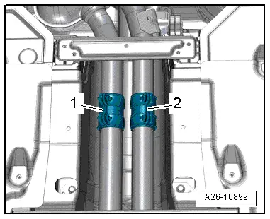
- loosen the clamping sleeves -1 and 2- and remove the rear section of the exhaust system. Refer to → Rep. Gr.26; Exhaust Pipes/Mufflers; Overview - Muffler.
 Note
Note
A second technician is needed to help remove the rear section of the exhaust system.
- Remove the driveshaft from the rear final drive. Refer to → Chapter "Drive Shaft, Removing and Installing from Rear Final Drive".
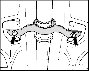
- Remove the driveshaft intermediate bearing mounting bolts -arrows-.
- Push the driveshaft forward and at the same time remove it from the rear final drive.
 Note
Note
- The driveshaft is supported by the heat shield under the intermediate bearing.
- The driveshaft can be bent all the way to the center joint without force. Bending the joint forcibly all the way can damage the center joint and/or the protective boot.
- Secure the driveshaft on the side to the subframe.

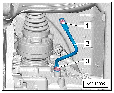
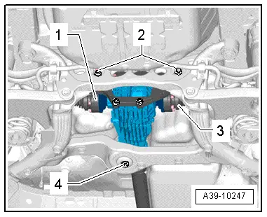
- Remove the bolt -3- for the potential equalization cable -2-.
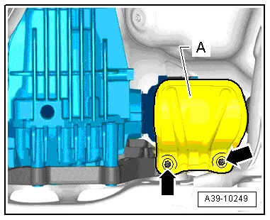
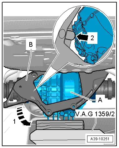
- Remove the left drive axle heat shield -A- from the crossmember/rear final drive-arrows-.
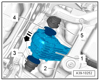
- Remove the left -1- and right -3- drive axles.
- Loosen the bolts -2- approximately three turns.
- Remove the bolt -4-.
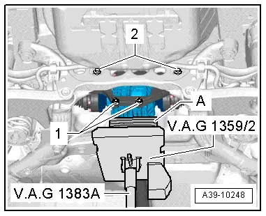
- Position the Engine and Gearbox Jack -VAS6931- and the Universal Transmission Support -VAG1359/2- and a block of wood -A- (approximately 80 mm tall) under the rear final drive.
 Note
Note
Pay attention that the Universal Transmission Support -VAG1359/2- does not make contact with the fuel tank.
- Remove the bolts -1- (lower bolts attaching the crossmember to the rear final drive) and -2-.
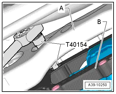
- Remove the two upper bolts that connect the crossmember -B- to the rear final drive.
- Guide the Socket - Xzn 12 -T40154- through the holes in the subframe -A-. Move the final drive to the left or right just a little, if necessary.
- Move the final drive -A- forward slightly.
- Turn the lower crossmember -B- direction of -arrow 1- and guide the final drive -arrow 2- and remove it.
 Note
Note
- A second technician must help with the next steps.
- Before raising the left rear suspension, secure the vehicle to the lifting arm on the hose using a Tensioning Strap -T10038-.
- Remove the Engine and Gearbox Jack -VAS6931- from under the final drive while a second technician keeps the rear final driving from falling down.
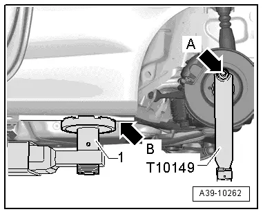
- Insert the Engine/Gearbox Jack Adapter - Wheel Hub Support - T10149- in the Engine and Gearbox Jack -VAS6931-.

- Attach the Engine/Gearbox Jack Adapter - Wheel Hub Support -T10149- using a wheel bolt -arrow A- to the left rear suspension wheel hub.
- Lift the left rear suspension using the Engine and Gearbox Jack -VAS6931- just until the support arm -1- on the vehicle hoist just starts to lift the vehicle -arrow B-.
 WARNING
- Do not raise or lower the vehicle when the Engine and Gearbox Jack -VAS6931- is underneath it.
- Do not leave the Engine and Gearbox Jack -VAS9631- under the vehicle longer than necessary.
- The second technician must now push the rear final drive -1- toward the left side of the vehicle in direction of -arrow-.
- Then guide the right drive axle -5- upward out of the final drive flange shaft -4-.
- Guide the left drive axle -3- out and then, together with the second technician, remove the final drive from the subframe -2- toward the rear.
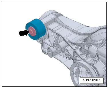
- If the rear final drive is replaced, the balance weight -arrow- must be rebuilt on the new rear final drive.
Installing
Install in reverse order of removal.
 WARNING
Handling the high-voltage cables:
- Do not stand on or place tools on the high-voltage cables or their components. This may damage the insulation.
- Do not bend or kink high-voltage cables as this may damage the insulation.
- The round high-voltage connectors are color coded with an exterior colored ring and mechanically coded with guide or code tabs. Observe the coding when connecting the round high-voltage connector in order to avoid mechanical damage to the high-voltage connector.
- With a second technician, position the rear final drive -1- on the subframe -2- in its installed position.
- Insert the left drive axle -3- into the final drive flange shaft.
- The second technician must now push the rear final drive -1- toward the left side of the vehicle in direction of -arrow-.
- Then install the right drive axle -5- into the final drive flange shaft -4-.
- Remove the Engine and Gearbox Jack -VAS6931- with the Engine/Gearbox Jack Adapter - Wheel Hub Support -T10149- from the left rear suspension.

- Position the Engine and Gearbox Jack -VAS6931- and the Universal Transmission Support -VAG1359/2- and a block of wood (approximately 80 mm tall) under the rear final drive -A-.
- Move the final drive -A- forward slightly.
- Turn the upper crossmember -B- opposite the direction of -arrow 1- to the left and insert it while guiding it past the final drive -arrow 2-.
- Tighten the four bolts connecting the crossmember -B- to the rear final drive diagonally. Tightening specification. Refer to -item 4-.
- Guide the Socket - Xzn 12 -T40154- through the holes in the subframe -A-. Move the final drive to the left or right just a little, if necessary.

- First tighten the bolt -2 and 4- hand-tight.
 Note
Note
For better illustration the Engine and Gearbox Jack -VAS6931- with the Universal Transmission Support -VAG1359/2- are not shown.
- Tighten the bolt -4-. Tightening specification. Refer to -item 3-.
- Tighten the bolts -2-. Tightening specification. Refer to -item2-.
- Remove the Engine and Gearbox Jack -VAS6931- from under the final drive.
- Tighten the left -1- and right -3- drive axles. Refer to → Suspension, Wheels, Steering; Rep. Gr.42; Drive Axle; Drive Axle, Removing and Installing.

- Tighten the potential equalization cable -2- to the rear final drive.
- Bolt tightening specification -3- on the final drive: 20 Nm

- Attach the left drive axle heat shield -A- to the crossmember/rear final drive -arrows--item 6-.

- Attach the driveshaft to the rear final drive.
- Attach the driveshaft intermediate bearing to the body free of tension. Tightening specification. Refer to -item 8-.
- Check the gear oil level in the rear final drive. Refer to → Chapter "Gear Oil, Checking Level, 0BC".
- Install the rear section of the exhaust system and align it so it is free of tension. Refer to → Rep. Gr.26; Exhaust Pipes/Mufflers; Overview - Muffler.
- Install the left rear wheel and tighten. Refer to → Suspension, Wheels, Steering; Rep. Gr.44; Wheels and Tires; Wheel Bolt Tightening Specifications.
Energizing the High-Voltage System
Only by using the Guided Fault Finding in the Vehicle Diagnostic Tester can the high-voltage system be restarted.
 DANGER!
Extremely dangerous high-voltage
Electrocution can lead to severe bodily injury or death
- The high-voltage system may only be re-energized by qualified personnel (Audi high-voltage technician).
- Only the Vehicle Diagnostic Tester via "Guided Fault Finding" can guarantee if the system has been re-energized.
- The qualified personnel (Audi high-voltage technician) restarts the vehicle.
- The qualified personnel (Audi high-voltage technician) marks the vehicle with a warning label.
 Note
Note
- Energizing the high-voltage system:
- Connect the Vehicle Diagnostic Tester
- Select the Guided fault finding mode
- Using the Go To button, move through the following menu points
- Function/component selection
- Body
- Electrical Equipment
- OBD-capable system
- 8C - hybrid battery management -J840
- 8C - hybrid battery management, functions
- 51 - High-voltage re-energizing (Rep.Gr. 93)

